Pull Forward
Plasma Display
Frame
Wall Mounting Unit
Lateral View
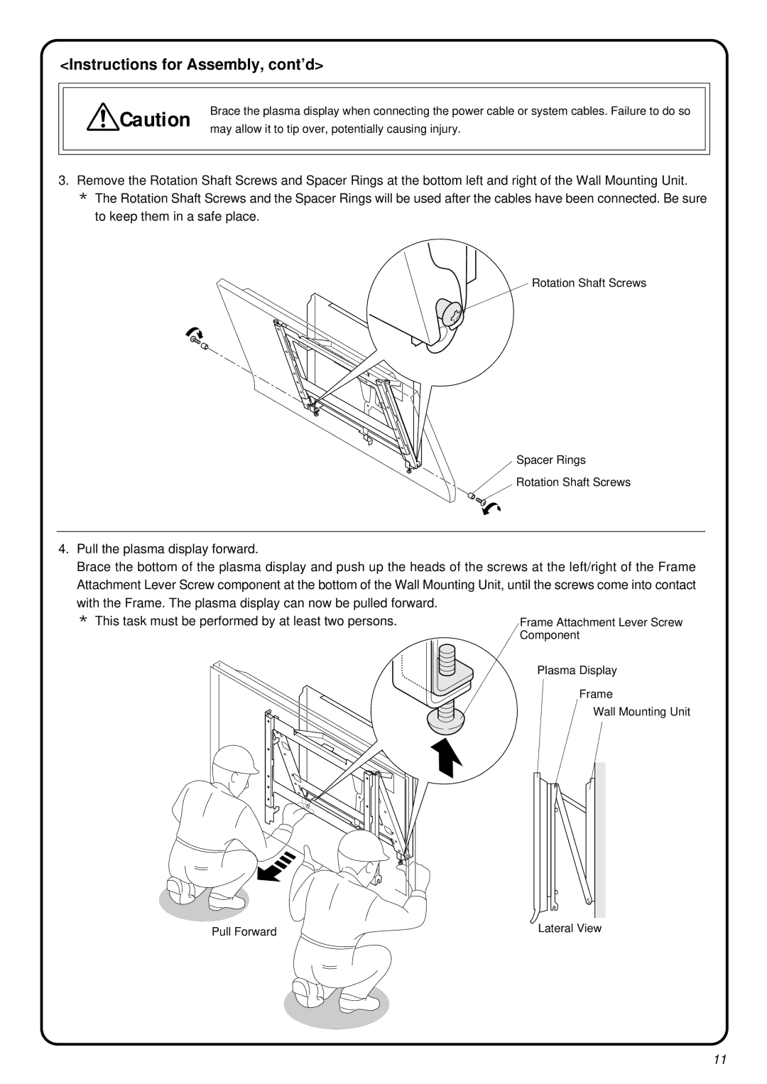
3. Remove the Rotation Shaft Screws and Spacer Rings at the bottom left and right of the Wall Mounting Unit. * The Rotation Shaft Screws and the Spacer Rings will be used after the cables have been connected. Be sure
to keep them in a safe place.
Rotation Shaft Screws
Spacer Rings Rotation Shaft Screws
4. Pull the plasma display forward.
Brace the bottom of the plasma display and push up the heads of the screws at the left/right of the Frame Attachment Lever Screw component at the bottom of the Wall Mounting Unit, until the screws come into contact with the Frame. The plasma display can now be pulled forward.
* This task must be performed by at least two persons.Frame Attachment Lever Screw Component
Brace the plasma display when connecting the power cable or system cables. Failure to do so may allow it to tip over, potentially causing injury.
<Instructions for Assembly, cont’d>
![]() Caution
Caution
11