 Controls and Features (cont.)
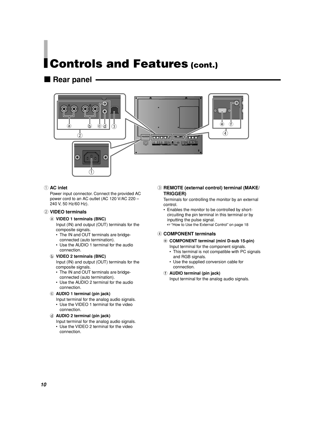
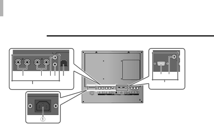
7Rear panel
a | b c d |
2
3
e f
4
1AC inlet
Power input connector. Connect the provided AC power cord to an AC outlet (AC 120 V/AC 220 – 240 V, 50 Hz/60 Hz).
2VIDEO terminals
a VIDEO 1 terminals (BNC)
Input (IN) and output (OUT) terminals for the composite signals.
•The IN and OUT terminals are bridge- connected (auto termination).
•Use the AUDIO 1 terminal for the audio connection.
bVIDEO 2 terminals (BNC)
Input (IN) and output (OUT) terminals for the composite signals.
•The IN and OUT terminals are bridge- connected (auto termination).
•Use the AUDIO 2 terminal for the audio connection.
cAUDIO 1 terminal (pin jack)
Input terminal for the analog audio signals.
•Use the VIDEO 1 terminal for the video connection.
dAUDIO 2 terminal (pin jack)
Input terminal for the analog audio signals.
•Use the VIDEO 2 terminal for the video connection.
3REMOTE (external control) terminal (MAKE/
TRIGGER)
Terminals for controlling the monitor by an external control.
•Enables the monitor to be controlled by short- circuiting the pin terminal in this terminal or by inputting the pulse signal.
☞“How to Use the External Control” on page 18
4COMPONENT terminals
e COMPONENT terminal (mini
•This terminal is not compatible with PC signals and RGB signals.
•Use the supplied conversion cable for connection.
fAUDIO terminal (pin jack)
Input terminal for the analog audio signals.
10