
TM-A9UCV, TM-A9U specifications
The JVC TM-A9U and TM-A9UCV are notable additions to the professional video production landscape, known for their reliability and performance in various broadcasting and video monitoring environments. Designed for use in studios, OB vans, and on-location shoots, these monitors blend advanced technology with user-friendly features, making them an indispensable tool for professionals in the industry.At the core of the TM-A9U and TM-A9UCV is a 9-inch LCD panel that delivers high-quality images with impressive color accuracy and clarity. The 16:9 aspect ratio ensures compatibility with modern video formats, while the resolution provides a clear and crisp picture, ideal for critical viewing applications. Both monitors support a wide range of input formats, including composite, S-Video, and component video, making them versatile options for diverse video setups.
One of the standout features of the TM-A9UCV is its built-in waveform monitor and vector scope, which are essential for broadcast professionals who need precise color and luminance adjustments. This functionality allows users to monitor and adjust video signals in real-time, ensuring that the final output meets industry standards and quality expectations.
The TM-A9U variant is equipped with standard features suitable for most video applications, while the TM-A9UCV expands upon this foundation by incorporating additional connectivity options and advanced features, making it ideal for sophisticated video workflows. Both models are designed for easy operation, with intuitive front-panel controls and clear menu navigation that allow users to customize settings quickly and efficiently.
The monitors are also built with durability in mind, featuring a compact and lightweight design suitable for transport and application in various settings. The robust casing ensures that they can withstand the rigors of field use, maintaining performance and reliability under demanding conditions.
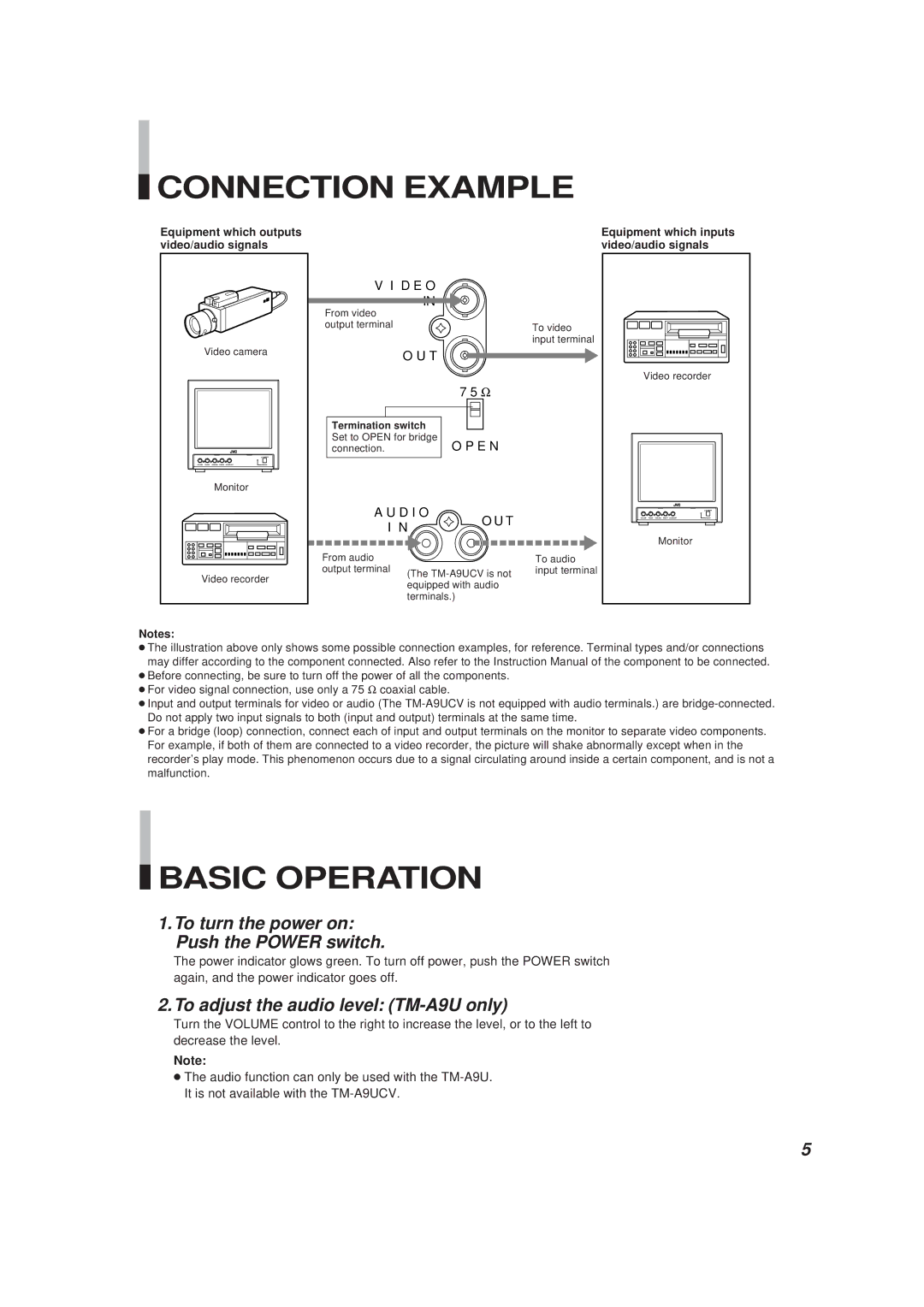
In terms of connectivity, the JVC TM-A9U and TM-A9UCV come equipped with multiple input and output options, allowing for seamless integration into various systems. These features make them suitable for use in a range of professional environments, including live event broadcasting, editing suites, and production studios.
In summary, the JVC TM-A9U and TM-A9UCV monitors offer a blend of performance, functionality, and ease of use, making them valuable tools for video professionals. Their compact design, advanced monitoring capabilities, and versatile input options provide users with the confidence to deliver high-quality video content in any scenario.