ASSEMBLY
![]() WARNING: Always be sure that the tool is switched off and unplugged from the power source before adjusting, adding accessories, or checking a function on the tool.
WARNING: Always be sure that the tool is switched off and unplugged from the power source before adjusting, adding accessories, or checking a function on the tool.
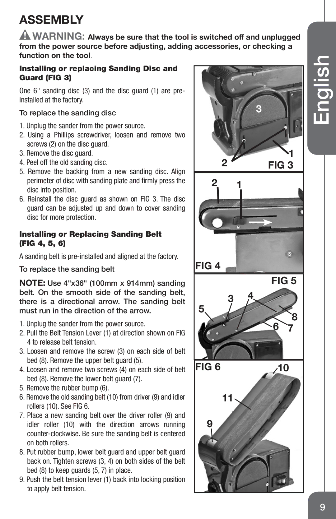
Installing or replacing Sanding Disc and Guard (FIG 3)
One 6" sanding disc (3) and the disc guard (1) are pre- installed at the factory.
To replace the sanding disc
1.Unplug the sander from the power source.
2.Using a Phillips screwdriver, loosen and remove two screws (2) on the disc guard.
3.Remove the disc guard.
4.Peel off the old sanding disc.
5.Remove the backing from a new sanding disc. Align perimeter of disc with sanding plate and firmly press the disc into position.
6.Reinstall the disc guard as shown on FIG 3. The disc guard can be adjusted up and down to cover sanding disc for more protection.
Installing or Replacing Sanding Belt (FIG 4, 5, 6)
A sanding belt is
To replace the sanding belt
NOTE: Use 4"x36" (100mm x 914mm) sanding belt. On the smooth side of the sanding belt, there is a directional arrow. The sanding belt
| 3 |
2 | 1 |
FIG 3 | |
2 | 1 |
FIG 4
FIG 5
3 4
English
must run in the direction of the arrow.
1. Unplug the sander from the power source. |
2. Pull the Belt Tension Lever (1) at direction shown on FIG |
4 to release belt tension. |
3. Loosen and remove the screw (3) on each side of belt |
bed (8). Remove the upper belt guard (5). |
5
8 ![]() 6 7
6 7
4. Loosen and remove two screws (4) on each side of belt |
bed (8). Remove the lower belt guard (7). |
5. Remove the rubber bump (6). |
6. Remove the old sanding belt (10) from driver (9) and idler |
rollers (10). See FIG 6. |
7. Place a new sanding belt over the driver roller (9) and |
idler roller (10) with the direction arrows running |
on both rollers. |
8. Put rubber bump, lower belt guard and upper belt guard |
back on. Tighten screws (3, 4) on both sides of the belt |
bed (8) to keep guards (5, 7) in place. |
9. Push the belt tension lever (1) back into locking position |
to apply belt tension. |
FIG 6 | 10 |
11
9
9