| WARNING: The belt tension lever is | |
| spring loaded. Be careful when pushing the | |
| tension lever back into place to avoid personal | |
English | injury. | |
Installing Table Assembly | ||
| ||
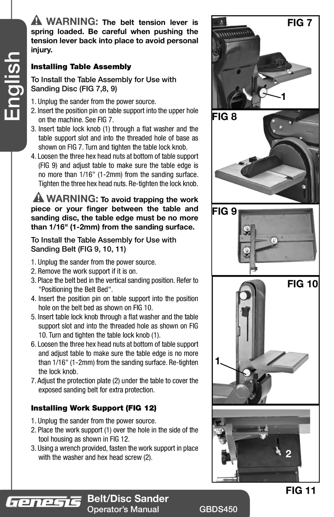
| To Install the Table Assembly for Use with | |
| Sanding Disc (FIG 7,8, 9) | |
| 1. Unplug the sander from the power source. | |
| 2. Insert the position pin on table support into the upper hole | |
| on the machine. See FIG 7. | |
| 3. Insert table lock knob (1) through a flat washer and the | |
| table support slot and into the threaded hole of base as | |
| shown on FIG 7. Turn and tighten the table lock knob. | |
| 4. Loosen the three hex head nuts at bottom of table support | |
| (FIG 9) and adjust table to make sure the table edge is | |
| no more than 1/16" | |
| Tighten the three hex head nuts. | |
| WARNING: To avoid trapping the work | |
| piece or your finger between the table and | |
| sanding disc, the table edge must be no more | |
| than 1/16" | |
| To Install the Table Assembly for Use with | |
| Sanding Belt (FIG 9, 10, 11) | |
| 1. Unplug the sander from the power source. | |
| 2. Remove the work support if it is on. | |
| 3. Place the belt bed in the vertical sanding position. Refer to | |
| "Positioning the Belt Bed". | |
| 4. Insert the position pin on table support into the position | |
| hole on the belt bed as shown on FIG 10. | |
| 5. Insert table lock knob through a flat washer and the table | |
| support slot and into the threaded hole as shown on FIG | |
| 10. Turn and tighten the table lock knob (1). | |
| 6. Loosen the three hex head nuts at bottom of table support | |
| and adjust table to make sure the table edge is no more | |
| than 1/16" | |
| the lock knob. | |
| 7. Adjust the protection plate (2) under the table to cover the | |
| exposed sanding belt for extra protection. |
Installing Work Support (FIG 12)
1.Unplug the sander from the power source.
2.Place the work support (1) over the hole in the side of the tool housing as shown in FIG 12.
3.Using a wrench provided, fasten the work support in place with the washer and hex head screw (2).
 Belt/Disc Sander
FIG 7
![]() 1
1
FIG 8
FIG 9
FIG 10
1
2
FIG 11
Operator’s Manual | GBDS450 |