CAUTION: Make all connections before plugging the System into an AC power outlet.
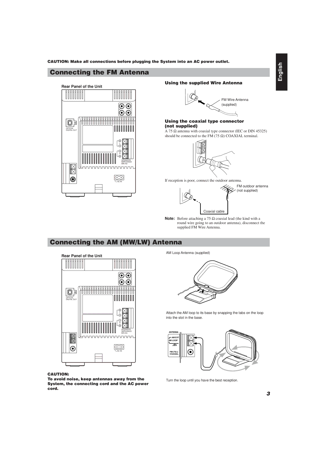
Connecting the FM Antenna
Using the supplied Wire Antenna
Rear Panel of the Unit
FM Wire Antenna
(supplied)
RL
English
OPTICAL
DIGITAL OUT
L
R
SPEAKERS
IMPEDANCE
MIN 4Ω
![]() AC IN
AC IN
Using the coaxial type connector (not supplied)
A 75 Ω antenna with coaxial type connector (IEC or DIN 45325) should be connected to the FM (75 Ω) COAXIAL terminal.
If reception is poor, connect the outdoor antenna.
FM outdoor antenna
(not supplied)
Coaxial cable
Note: Before attaching a 75 Ω coaxial lead (the kind with a round wire going to an outdoor antenna), disconnect the supplied FM Wire Antenna.
Connecting the AM (MW/LW) Antenna
AM Loop Antenna (supplied)
Rear Panel of the Unit
RL
OPTICAL
DIGITAL OUT
L
R
SPEAKERS
IMPEDANCE
MIN 4Ω
![]() AC IN
AC IN
Attach the AM loop to its base by snapping the tabs on the loop into the slot in the base.
ANTENNA
AM EXT
AM LOOP
FM (75Ω)
COAXIAL
CAUTION:
To avoid noise, keep antennas away from the System, the connecting cord and the AC power cord.
Turn the loop until you have the best reception.
3
