VN-T216VPRU specifications
The JVC VN-T216VPRU is a sophisticated network camera designed for versatile surveillance applications. This high-performance device showcases JVC's commitment to innovation, incorporating advanced features and technologies that meet the demands of modern security environments.One of the standout characteristics of the VN-T216VPRU is its high-definition imaging capability. The camera boasts a 2MP sensor, capturing clear and detailed video at resolutions of up to 1920 x 1080 pixels. This ensures that users can monitor their environments with exceptional clarity, making it easier to identify subjects and analyze events in real-time.
The VN-T216VPRU utilizes advanced image processing technologies to enhance video quality under varying lighting conditions. With features like Wide Dynamic Range (WDR) functionality, the camera excels in challenging environments with high contrast lighting. This allows it to capture clear images in both bright and dark areas simultaneously, improving overall scene visibility.
User convenience is further enhanced through the camera’s remote access capabilities. The VN-T216VPRU supports various network protocols, enabling users to access and control the camera from anywhere using a smartphone, tablet, or computer. This remote functionality is a significant asset for security personnel needing to monitor multiple locations without being physically present.
Another noteworthy feature is the camera's advanced compression technology. The VN-T216VPRU is equipped with H.265 compression, significantly reducing bandwidth and storage requirements while maintaining high image quality. This allows for efficient video storage over extended periods, making it a cost-effective solution for many surveillance needs.
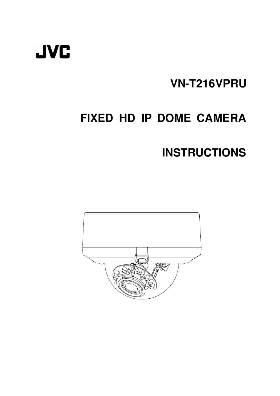
Durability is a key consideration in the design of the VN-T216VPRU. The camera is built to withstand harsh environmental conditions, making it suitable for both indoor and outdoor installations. With an IP66 rating, it is protected against dust and water ingress, ensuring reliable operation regardless of the surroundings.
Furthermore, the VN-T216VPRU is equipped with motion detection capabilities, alerting users to potential security breaches. This feature can be customized, providing flexibility depending on specific surveillance needs.
In summary, the JVC VN-T216VPRU is a robust network camera that combines high-definition imaging, advanced processing technologies, remote access capabilities, efficient compression, and durability, making it an ideal choice for comprehensive surveillance solutions.