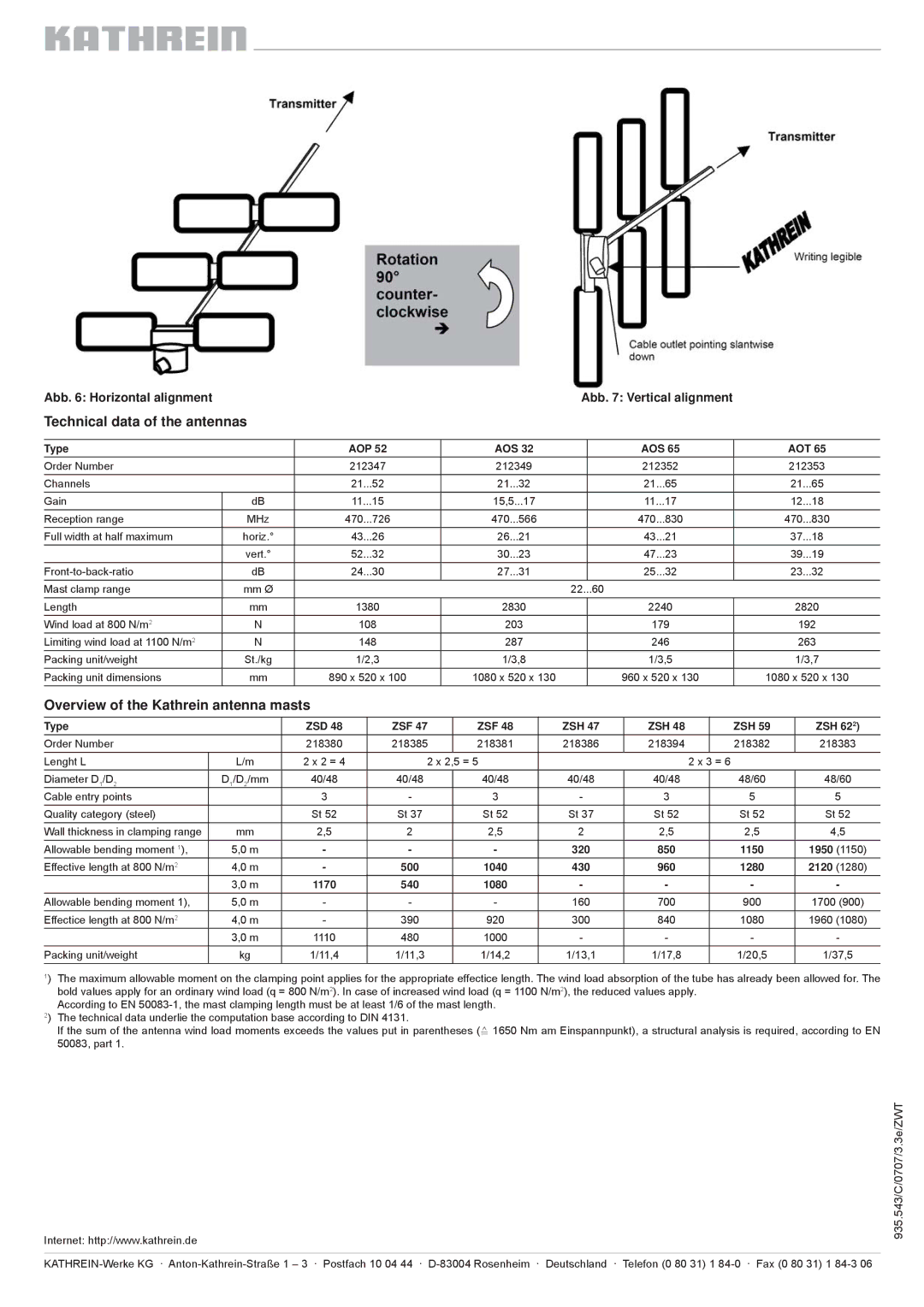
Abb. 6: Horizontal alignment |
|
|
|
|
|
|
|
| Abb. 7: Vertical alignment |
|
|
| |||||
Technical data of the antennas |
|
|
|
|
|
|
|
|
|
|
|
|
|
| |||
|
|
|
|
|
|
|
|
|
|
|
|
|
|
|
|
|
|
Type |
|
| AOP 52 |
|
| AOS 32 |
|
|
| AOS 65 |
| AOT 65 | |||||
Order Number |
|
| 212347 |
| 212349 |
|
|
| 212352 |
|
| 212353 | |||||
Channels |
|
| 21...52 |
| 21...32 |
|
|
| 21...65 |
|
| 21...65 | |||||
Gain | dB | 11...15 |
| 15,5...17 |
|
|
| 11...17 |
|
| 12...18 | ||||||
Reception range | MHz | 470...726 |
| 470...566 |
|
|
| 470...830 |
|
| 470...830 | ||||||
Full width at half maximum | horiz.° | 43...26 |
| 26...21 |
|
|
| 43...21 |
|
| 37...18 | ||||||
|
| vert.° | 52...32 |
| 30...23 |
|
|
| 47...23 |
|
| 39...19 | |||||
dB | 24...30 |
| 27...31 |
|
|
| 25...32 |
|
| 23...32 | |||||||
Mast clamp range | mm Ø |
|
|
|
|
|
| 22...60 |
|
|
|
|
|
| |||
Length | mm | 1380 |
| 2830 |
|
|
| 2240 |
|
| 2820 | ||||||
Wind load at 800 N/m2 | N | 108 |
| 203 |
|
|
| 179 |
|
| 192 | ||||||
Limiting wind load at 1100 N/m2 | N | 148 |
| 287 |
|
|
| 246 |
|
| 263 | ||||||
Packing unit/weight | St./kg | 1/2,3 |
| 1/3,8 |
|
|
| 1/3,5 |
|
| 1/3,7 | ||||||
Packing unit dimensions | mm | 890 x 520 x 100 |
| 1080 x 520 x 130 |
|
| 960 x 520 x 130 | 1080 x 520 x 130 | |||||||||
Overview of the Kathrein antenna masts |
|
|
|
|
|
|
|
|
|
|
|
| |||||
|
|
|
|
|
|
|
|
|
|
|
|
|
|
|
|
| |
Type |
|
| ZSD 48 |
| ZSF 47 |
| ZSF 48 |
| ZSH 47 |
| ZSH 48 |
| ZSH 59 |
| ZSH 622) | ||
Order Number |
|
| 218380 |
| 218385 |
| 218381 |
| 218386 |
| 218394 |
| 218382 |
| 218383 | ||
Lenght L |
| L/m |
| 2 x 2 = 4 |
| 2 x 2,5 = 5 |
|
|
|
| 2 x 3 = 6 |
|
|
| |||
Diameter D1/D2 |
| D1/D2/mm |
| 40/48 |
| 40/48 |
| 40/48 |
| 40/48 |
| 40/48 |
| 48/60 |
| 48/60 | |
Cable entry points |
|
|
| 3 |
| - |
| 3 |
| - |
|
| 3 |
| 5 |
| 5 |
Quality category (steel) |
|
|
| St 52 |
| St 37 |
| St 52 |
| St 37 |
| St 52 |
| St 52 |
| St 52 | |
Wall thickness in clamping range |
| mm |
| 2,5 |
| 2 |
| 2,5 |
| 2 |
|
| 2,5 |
| 2,5 |
| 4,5 |
Allowable bending moment 1), |
| 5,0 m |
| - |
| - |
| - |
| 320 |
| 850 |
| 1150 |
| 1950 (1150) | |
Effective length at 800 N/m2 |
| 4,0 m |
| - |
| 500 |
| 1040 |
| 430 |
| 960 |
| 1280 |
| 2120 (1280) | |
|
| 3,0 m |
| 1170 |
| 540 |
| 1080 |
| - |
|
| - |
| - |
| - |
Allowable bending moment 1), |
| 5,0 m |
| - |
| - |
| - |
| 160 |
| 700 |
| 900 |
| 1700 (900) | |
Effectice length at 800 N/m2 |
| 4,0 m |
| - |
| 390 |
| 920 |
| 300 |
| 840 |
| 1080 |
| 1960 (1080) | |
|
| 3,0 m |
| 1110 |
| 480 |
| 1000 |
| - |
|
| - |
| - |
| - |
Packing unit/weight |
| kg |
| 1/11,4 |
| 1/11,3 |
| 1/14,2 |
| 1/13,1 |
| 1/17,8 |
| 1/20,5 |
| 1/37,5 | |
1) The maximum allowable moment on the clamping point applies for the appropriate effectice length. The wind load absorption of the tube has already been allowed for. The bold values apply for an ordinary wind load (q = 800 N/m2). In case of increased wind load (q = 1100 N/m2), the reduced values apply.
According to EN
If the sum of the antenna wind load moments exceeds the values put in parentheses (≙ 1650 Nm am Einspannpunkt), a structural analysis is required, according to EN 50083, part 1.
Internet: http://www.kathrein.de
935.543/C/0707/3.3e/ZWT