LOGO! installation Wiring
Configuring Logo
Manual
04/2011 Preface
Legal information
Qualified Personnel
Proper use of Siemens products
Trademarks
Preface
Purpose of this manual
LOGO!s place in information technology
Guide
New features of the LOGO! 0BA7 device series
Valid range of this manual
New features of the LOGO! 0BA6 device series
Extended real-time clock backup time
Support of data logging
New special function blocks
Additional differences compared to previous devices
0BA6 versus device series 0BA0 to 0BA5
0BA7 versus devices series 0BA0 to 0BA6
Additional support
Preface
Table of contents
Table of contents
137
279
317
319
349
351
Getting started with Logo
Heres Logo
What LOGO! can do for you
Which devices are available?
Which expansion modules are available?
Which display modules are available?
Features of the LOGO! TD
Which communication modules are available?
Its your choice
Getting started with Logo
LOGO! structure
%$ /2*25& %$ /2*25&
%$ /2*25& /2*25&
RUN/STOP LED
LOGO! AM2
LOGO! AM2 AQ 0 .. V DC or 0/4 .. mA
LOGO! CM EIB/KNX
How to identify Logo
LOGO! TD
Symbols
Symbol Designation Supply voltage Inputs Outputs Properties
Versions
Symbol Name Power supply Inputs Outputs
Expansion modules
Symbol Name Supply voltage Display
Communication modules
Text Display Module
Certification and approvals
ID for Australia
ID for Korea
Recycling and Disposal
LOGO! installation and wiring
General guidelines
What you must note when installing
Safety of electronic control equipment
Introduction Reliability
Carrying out tests
Risks
Important information
Modular LOGO! setup
Maximum LOGO! network setup 0BA7 only
Maximum LOGO! 0BA7 network setup
Typical LOGO! 0BA7 network setup is shown below
Maximum setup with expansion and communication modules
High-speed/optimal communication performance
Setup with different voltage classes
Rules
LOGO! Base Module Expansion modules
Expansion module Additional expansion modules
Compatibility
Installing/removing Logo
Dimensions
DIN rail mounting
Mounting
%$ %$
%$ %$
Removal
Wall-mounting
Drilling template for wall-mounting
Mounting the LOGO! TD
XX`U\RWU\
\RWU\
Labeling Logo
Wiring Logo
Connecting the power supply
Connecting Logo
Circuit protection with AC voltage
Circuit protection with DC voltage
Connecting the LOGO! TD power supply
Connecting LOGO! inputs
Sensor characteristics for Logo
Requirements
LOGO! 12/24RCE LOGO! 24/24o
Sensor connections
Restrictions
Remedy
Connecting a potentiometer to inputs I1, I2, I7
Voltage Potentiometer
LOGO! 12/24.... and Logo
Logo
Connecting a two-wire sensor to the LOGO! AM2
LOGO! AM2
LOGO! AM2 PT100
LOGO! AM2 RTD
Connecting outputs
LOGO! AM2 AQ
Connecting the EIB bus
Networking on the EIB bus
Connecting the AS interface bus
Networking on the AS interface bus
Logic Assignments
LOGO! system
Inputs Output data bits
Outputs Input data bits
Connecting modems 0BA6 only
Connecting the Ethernet interface 0BA7 only
LOGO! ...E
Requirements for the network cable
Ethernet status LEDs
Switching the LOGO!/Power On
Putting into operation
HPSW\
1R3URJUDP 3UHVV6
Putting a CM EIB/KNX into operation
Operating states
LOGO! Base Module operating states
LOGO! expansion modules, operating states
LED RUN/STOP is lit Green RUN Red Stop Orange/Yellow
CM AS Interface, communication states
CM AS Interface, behavior on communication failure
CM EIB/KNX, communication states
CM EIB/KNX, behavior on communication failure
Programming Logo
Getting started with Logo
Connectors
Example of a configuration with several modules
LOGO! is equipped with inputs and outputs
LOGO!s connectors
LOGO! has the following connectors
Connectors
EIB inputs/outputs
Functions of the application program
Blocks and block numbers
Blocks
Logic operations
9LHZRIWKH/2*2GLVSOD\
ุ
ุ
From circuit diagram to LOGO! program
View of a circuit diagram
Creating this circuit with Logo
Wiring
Unused inputs
Wiring example
Rule 1 Changing the operating mode
Four golden rules for operating Logo
Rule 2 Outputs and inputs
Rule 3 Cursor and cursor movement
Rule 4 Planning
Overview of LOGO! menus
3URJUDP
6WDUW
6WRS
LOGO! 0BA7 menus
3URJUDP &DUG 6HWXS 6WDUW
Selecting programming mode
Writing and starting the circuit program
GLW3UJ
4
LOGO!s programming menu is as shown below
Circuit diagram
First circuit program
Circuit program
Circuit program input
4
4
% ุ 4
% ุ 4
% ุ 4
ุ
4
%
ุ
Assigning a circuit program name
GLW3UJ !GLW1DPH $4 0HPRU\
Password for circuit program protection
Assigning a program password from the LOGO! Basic
GLW
2OG
Changing the password from the LOGO! Basic
2OG 1HZ
Deactivating the password from the LOGO! Basic
Password Wrong Password
7
YHUVLRQ6
7 YHUVLRQ666
6HWXS
Main menu of the LOGO! TD version ES7
Switching LOGO! to RUN mode
LVSOD\ILHOGRI/2*2LQ581PRGH
What is meant by LOGO! is in RUN?
Ⴋ
Status indication on the display
XVLQJRXUHDPSOH
Second circuit program
Modifying circuits
Editing the circuit program
4
ൻ64
7UJ 3DU
Adding a block to a circuit program
Setting the time
Assigning block parameters
Showing/hiding parameters the parameter protection mode
P
Enabling/disabling retentivity
Closing the programming mode
0R
Verification of the circuit program
Deleting a block
4
Deleting block groups
Correcting programming errors
Selecting analog output values for RUN/STOP transition
$4LQ6WRS $47\SH
Defining a specific analog output value
Defining the type of analog outputs
Deleting the circuit program and password
LOGO! 0BA6 main menu
LOGO! 0BA7 main menu
Summertime/wintertime conversion
3DVVZRUG ==
\QF
2Q 2II
Enabling summertime/wintertime conversion
Start of summertime End of summertime Time zone Difference Δ
2II 7LPH 2Qൺ8
00
User-defined parameters
00
2II 7LPH 2Qൺ
Synchronization
0HQX/DQJ
6HW&ORFN
\QF 2II
Enabling synchronization
Configuring additional functions for LOGO! 0BA7 only
New menu commands
UDF and Data Log
Network digital and analog I/O
Configuring network settings
Configuring the network settings
Configuring a UDF User-Defined Function
6XEQHWPDVN
Transferring the circuit program to LOGO!Soft Comfort
Configuring the Data Log
Viewing network inputs/outputs
Viewing network connectors in Logo
4
4
14 1$4
Changing LOGO! to normal/slave mode
Normal mode versus slave mode
Changing LOGO! from normal mode to slave mode
3DVVZRUG
1RUPDO 6ODYH 3DVVZRUG
Rqilj
0DVWHU,3
Changing LOGO! from slave mode to normal mode
Assigning a password from the Logo
1RUPDO 6ODYH 3DVVZRUG
1RUPDO 6ODYH !3DVVZRUG
Changing the password from the Logo
Deactivating the password from the Logo
Diagnosing errors from Logo
Viewing error information
YHUVLRQ
Clearing error information
Toggling an error alert
OHDUHUURU
OHDUDOO
Memory space and circuit program size
Memory areas
Resources available in Logo
Program memory
Memory requirements 0BA6
Function
Rem Memory Basic functions
Special functions
Memory requirements 0BA7
Function Program Rem Memory
Function Program Rem Memory Basic functions
Utilization of memory areas
Calculating memory requirements
Sample circuit program contains
Example
Indication of available memory space
136
List contents
LOGO! functions
If not all is shown
Constants and connectors Co
Inputs Digital inputs
Analog inputs
Outputs Digital outputs
Analog outputs
Flag blocks
Startup flag
Backlight flags M25 and M26
Open connectors
Message text character set flag M27
Shift register bits
Cursor keys
Network digital inputs
Network analog inputs
Network digital outputs
Network analog outputs
Basic functions list GF
Function logic table
Negation, inverter
Timing diagram for the and with edge evaluation
With edge evaluation
Nand not
Nand function logic table
Timing diagram for the Nand with edge evaluation
Nand with edge evaluation
5 or
ุ
Or function logic table
NOR not or
NOR function logic table
XOR exclusive or
Not Negation, Inverter
XOR function logic table
Not function logic table
Special Functions
Designation of the inputs
Logical inputs
Connector X at SF inputs
Time response
K
Parameter inputs
Backup of the real-time clock
Accuracy of the timer weekly/yearly timer
Accuracy of T
Retentivity
Parameter protection
Calculating the gain and offset of analog values
Mathematical rule
Gain and offset calculation
Parameter Minimum Maximum
Example of analog values
Special functions list SF
View in Logo Name of the special function Rem Times
View in Logo Name of the special function Rem
Counter
Analog
Miscellaneous
On-delay
Symbol in Logo Wiring Description
Short description
Name of the special function Rem
Timebase Max. value Min. resolution Accuracy
Valid ranges of the timebase, if T = parameter
5 ൺ%V
Timebase Max. value Meaning Accuracy
Timing diagram
K 7D K
ൺ%P
Functional description
Off-delay
165
3 On-/Off-delay
Parameters TH and TL
167
Retentive on-delay
169
Wiping relay pulse output
171
Edge triggered wiping relay
TL/TH
Timing diagram a
Timing diagram B
Setting the Par parameter
Press
Asynchronous pulse generator
Timing diagram Functional description
Random generator
Parameter TH and TL
178
Stairway lighting switch
Parameter T, T! and T!L
180
7D V
Multiple function switch
Parameters T, TL,T! and T!L
183
184
Weekly timer
Timing diagram three examples
Symbol in Logo Wiring Description 0BA6
Symbol in Logo Wiring Description 0BA7
07766 2Q 2II
07766 2Q 2II
Parameter assignment screen form LOGO! 0BA6
Parameter assignment screen form LOGO! 0BA7
Setting the weekly timer
Days of the week
On-/Off-times
07766 2Q 2II
07766 2Q 2II
7 2Q 2II
Cam3
Result
Yearly timer
Timing diagrams
21 00
21 00
21 00
21 00
21 00
21 00
21 00
Backup of the real-time clock
Sample configuration
21 00
Astronomical clock 0BA7 only
Longitude
Latitude
Zone
$67
ಬರ
1257+
ಬರ
Dwlwxgh
Possible timebase settings
Stopwatch 0BA7 only
Parameters TB
199
PV
PV
15 Up/down counter
Parameters On and Off
Calculation rule
QW
Hours counter
Parameter MI
Viewing the MI, MN and OT values
P
P 5 4ൺ5Q 5 %K
Limit value of OT
P
P
Threshold trigger
Parameter GT
211
2II
2Q 2II ID
Analog threshold trigger
Gain and offset parameters
Parameter p number of decimals
Timing diagram a Function with negative difference Δ
Analog differential trigger
Timing diagram B Function with positive difference Δ
2II
Analog comparator
219
220
Example
Application Internal mapping
Reducing the input response of the analog comparator
Function block diagram
Analog watchdog
Parameters Delta1 and Delta2
225
ෙ
Analog amplifier
Analog output
Scaling an analog input value
Timing diagram Switching response
Latching relay
Comment
Short pulse at the input sets and resets the output
Pulse relay
Status diagram
Par
Trg
Global Message Text Settings
Message texts
Chinese Character Set
Programming Global Message Text Parameters
Message Text Function Block
234
Restriction
Message Ticking
This is how two message texts could be shown
Example Tick Message Character by Character
$FN
$FN 2Q
0VJHVW
1R
1R
Visible parameters or process variables
Special function
240
Editing message texts
Changing parameters in the active message text
Key input simulation in the active message text
242
Factory setting
Softkey
6ZLWFK
6ZLWFK 2Q
Shift register
246
Setting the Par parameter 0BA6
Setting the Par parameter 0BA7
Analog multiplexer
Parameters
ൺ% ൺ% S
ൺ% ൺ% $4
Analog Ramp
252
Parameters L1, L2
Timing diagram for AQ
PI controller
Parameters SP and Mq
Parameters KC, TI
Sampling time
Parameter sets
63ൺ%
$4
Pulse Width Modulator PWM
Parameters p number of decimals
Examples with Timing Diagrams
264
Mathematic instruction
266
Possible errors Zero division and overflow
Examples
Result
Mathematic instruction error detection
Mathematic instruction error detection logic table
Parameter MathBN
Err
270
Timing diagram example
Analog filter 0BA7 only
6Q
35 Max/Min 0BA7 only
Mode
Parameter Mode
Average value 0BA7 only
6W V 6Q
278
UDF User-Defined Function 0BA7 only
User-Defined Function UDF
Editing elements connected to a UDF block
4 4
Editing elements to the inputs of a UDF block
0
ൺ8 0
Editing elements to the outputs of a UDF block
Press to see the final view
Data Log 0BA7 only
/
/
Editing elements connected to the Data Log block
/
/
Configuring Logo
Selecting parameter assignment mode
Menu command ①
%$ ႣႭ
%$
Menu command ②
Menu command ③
Menu command ④
Menu command ⑤
Parameters
Selecting the parameters
6WRS
V
V
Current timer value
Modifying parameters
V 7D V
P
Current value of a counter
Current value of an hour counter
Current value of a threshold trigger
Setting the default values for Logo
Setting the time of day and date LOGO! ... C
Setting the display contrast and backlight choice
Rqwudvw
To set the backlight choice in programming mode
Rqwudvw DFN/LJKW
$OZD\V2Q Ghidxow
Setting the menu language
To set the menu language in parameter assignment mode
To set the menu language in programming mode
To reset LOGO! to its default language setting
Setting the number of AIs in the LOGO! Basic
To set the number of AIs in programming mode
See also
Setting the start screen
Orfn
To select the start screen
301
302
Applicable cards
Compatability Old memory cards in newer LOGO! modules
Upward compatibility of circuit programs
Password Protection Editing Copying Deleting
Security function CopyProtect
Unprotected cards
Protected cards
Assigning a security function
Enabling the security function
Inserting and removing the card from Logo
%$
Removing the SD card slot cap from LOGO! 0BA7
Removing the SD card
Copying data from LOGO! to the card
Copying data from LOGO! to the card manually
Copying data from LOGO! 0BA7 to the SD card automatically
Generating the data log on the SD card
Copying data from the card to Logo
Automatic copying during the startup of Logo
Copying by means of the Card menu
LOGO! software
LOGO! software
Updates and info
LOGO! alternatives
LOGO!Soft Comfort
Upgrading previous LOGO!Soft Comfort versions
Connecting LOGO! to a PC
Connecting the PC cable for LOGO! 0BA6 only
Connecting the USB PC cable for LOGO! 0BA6 only
Switching LOGO! to PC ↔ LOGO! mode
Closing the PC ↔ LOGO! mode
Connecting a standard Ethernet cable for LOGO! 0BA7 only
Applications
Benefits of Logo
Do you want more Info?
Do you have any suggestions?
Technical data
General technical data
Safety to IEC
Ambient mechanical conditions
Electromagnetic compatibility EMC
Cycle time
Technical data Logo
LOGO! 230RCo Power supply
Digital inputs
LOGO! 230RCo
Digital outputs
323
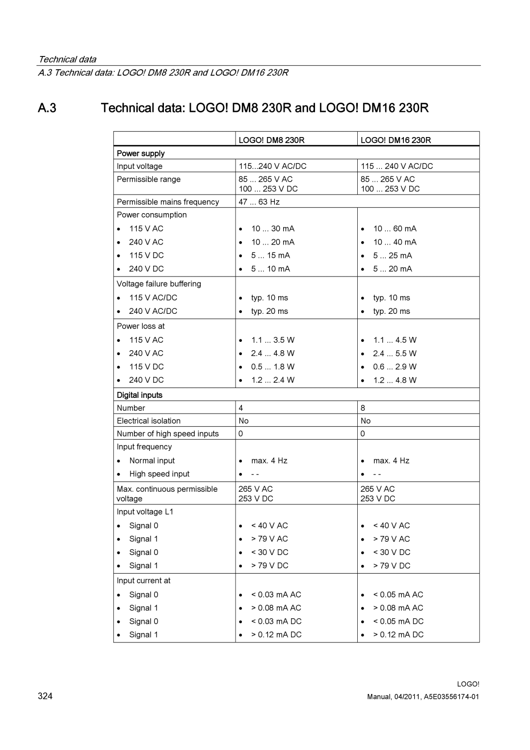
Technical data LOGO! DM8 230R and LOGO! DM16 230R
LOGO! DM8 230R LOGO! DM16 230R Power supply
LOGO! DM8 230R LOGO! DM16 230R
LOGO! 24o LOGO! 24Co Power supply
LOGO! 24C
LOGO! 24o LOGO! 24Co
Analog inputs
Technical data LOGO! DM8 24 and LOGO! DM16
LOGO! DM8 LOGO! DM16 Power supply
LOGO! DM8 LOGO! DM16
Technical data LOGO! 24RC
LOGO! 24RCo
331
Technical data LOGO! DM8 24R and LOGO! DM16 24R
LOGO! DM16 24R
333
Technical data LOGO! 12/24... LOGO! DM8 12/24R
335
336
Switching capacity/service life of the relay outputs
Technical data LOGO! AM2
LOGO! AM2
Technical data LOGO! AM2 PT100
Sensor inputs
Technical data LOGO! AM2 RTD
Technical data LOGO! AM2 AQ
Analog outputs
Technical data CM EIB/KNX
Technical data CM AS Interface
CM AS Interface Mechanical data
Technical data LOGO!Power 12
Technical data LOGO!Power 24
LOGO! Power 24 V / 1.3 a Input data LOGO! Power 24 V / 2.5 a
Technical data LOGO! Contact 24/230
LOGO! Power 24 V / 1.3 a 24 V / 2.5 a
Switching capacity
Contact
Technical data LOGO! TD Text Display
Mounting hole dimensions
Degree of protection
Connection distance
Technical data Battery information for LOGO! battery cards
Battery information for LOGO! Battery cards
Manufacturer
Type
Determining the cycle time
ID
Test program
Explanation
LOGO! without display LOGO! Pure
Less is definitely more
Creating a circuit program without operator panel
Operating characteristics
Startup characteristics
Operating status indication
Reading current data
LOGO! menu structure
LOGO! Basic
Menu overview 0BA6
0BA7
Main menu ESC / Stop 0BA6
Programming menu ESC / Stop → Program
Setup menu ESC / Stop → Setup
Transfer menu ESC / Stop → Card
Start Menu RUN
Fohdu
Diagnostic menu ESC / Stop → Diagnostic 0BA7 only
Network menu ESC / Stop → Network 0BA7 only
358
Menu overview LOGO! TD version ES6 or earlier
LOGO! TD version ES7
Main menu ESC / Stop LOGO! TD version ES6 or earlier
Start menu LOGO! Basic in RUN
PDPHVVDJHWHWV
Diagnostic menu in LOGO! TD version ES7, for LOGO! 0BA7 only
Network menu in LOGO! TD version ES7, for LOGO! 0BA7 only
Order numbers
Modules
Variant Designation Order number
Accessories
Accessories Designation Order number
Abbreviations
UDF
Abbreviations
Index
Index
Index
Index
XE \* Mergeformat
372