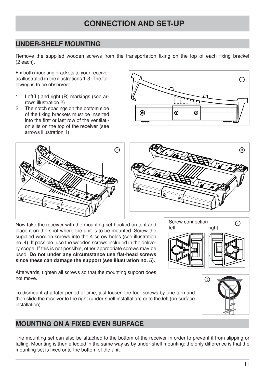
UFS 640si specifications
The Kathrein UFS 640si is a sophisticated satellite receiver that has earned a reputation for its reliability and advanced features, catering to avid television viewers and technology enthusiasts alike. This model, designed for the reception of digital satellite television, promises high-quality performance and a user-friendly experience.One of the standout features of the UFS 640si is its support for high definition (HD) broadcasting. The receiver can display crystal-clear, sharp images, providing viewers with an immersive visual experience. With its ability to decode multiple formats, including MPEG-2 and MPEG-4, the UFS 640si ensures compatibility with a wide range of satellite channels, allowing users to enjoy an extensive selection of programming.
The receiver is equipped with a powerful dual-core processor, which significantly enhances its performance and responsiveness. This processing capability enables quick channel switching, seamless menu navigation, and efficient handling of multiple tasks simultaneously, making the overall user experience smooth and enjoyable.
Connectivity is another key strength of the Kathrein UFS 640si. The device comes standard with an HDMI output, ensuring high-quality audio and video transmission to modern televisions. Additionally, it features USB ports for external storage devices, enabling users to record their favorite shows and pause live television, a feature that adds convenience to the viewing experience. The receiver also supports various multimedia formats, allowing playback of videos, images, and music directly from USB-connected devices.
Furthermore, the UFS 640si includes networking capabilities, allowing for easy integration into home networks. Users can access online services and additional content through its Ethernet port, expanding entertainment options beyond traditional broadcasting.
The user interface of the Kathrein UFS 640si is intuitive and easy to navigate, making it accessible for both tech-savvy users and those new to satellite receivers. The system includes programmable electronic program guides (EPG) that help viewers keep track of upcoming shows and plan their viewing schedule effectively.
In conclusion, the Kathrein UFS 640si satellite receiver stands out due to its comprehensive features, robust performance, and user-friendly design, making it an ideal choice for anyone looking to enhance their television viewing experience.

