_1_
r
Side
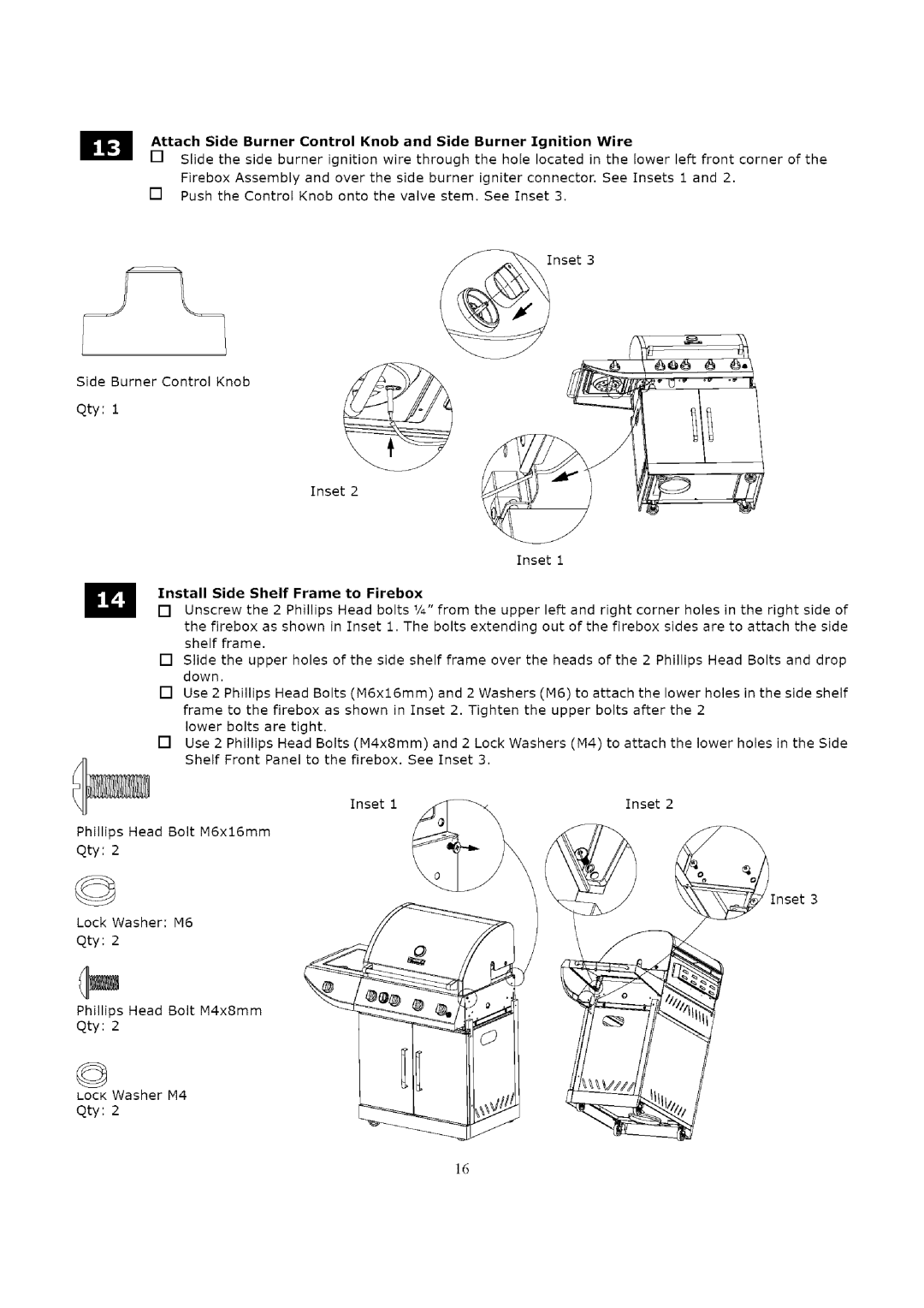
Attach Side | Burner | Control Knob | and | Side | Burner | Ignition | Wire | lower | left front corner of the | |||
[] | Slide the | side burner | ignition | wire through | the hole | located | in the | |||||
| Firebox Assembly | and | over | the | side | burner igniter | connector. | See | Insets | 1 and 2. | ||
[] | Push the | Control | Knob onto the valve stem. | See Inset 3. |
|
|
| |||||
Inset 3
Burner Control Knob
qty: 1
Inset 2
Inset 1
Install Side Shelf Frame to Firebox
[] Unscrew the 2 Phillips Head bolts ¼" from the upper left and right corner holes in the right side of the firebox as shown in Inset 1. The bolts extending out of the firebox sides are to attach the side shelf frame.
[] Slide the upper holes of the side shelf frame over the heads of the 2 Phillips Head Bolts and drop down.
[] Use 2 Phillips Head Bolts (M6x16mm) and 2 Washers (M6) to attach the lower holes in the side shelf frame to the firebox as shown in Inset 2. Tighten the upper bolts after the 2
lower bolts are tight.
[] Use 2 Phillips Head Bolts (M4x8mm) and 2 Lock Washers (M4) to attach the lower holes in the Side Shelf Front Panel to the firebox, See Inset 3.
Inset 1Inset 2
Phillips | Head | Bolt | M6x16mm | |
qty: | 2 |
|
|
|
© |
|
|
| Inset 3 |
Lock | Washer: | M6 |
| |
qty: | 2 |
|
|
|
Phillips | Head | Bolt | M4x8mm | |
Qty: | 2 |
|
|
|
© |
|
|
|
|
LOCK Washer | M4 |
| ||
qty: | 2 |
|
|
|
16
