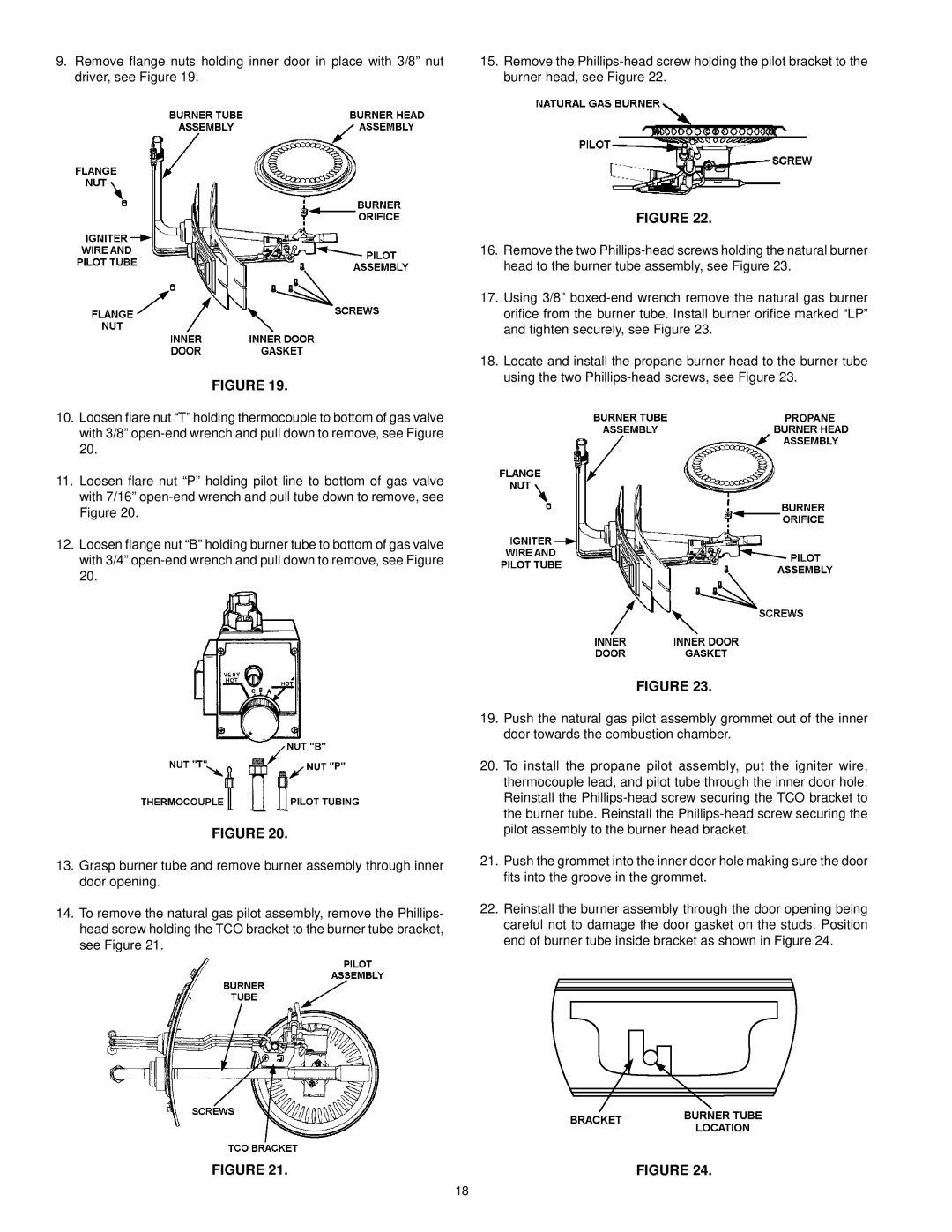
9.Remove flange nuts holding inner door in place with 3/8” nut driver, see Figure 19.
15.Remove the
FIGURE 19.
10.Loosen flare nut “T” holding thermocouple to bottom of gas valve with 3/8”
11.Loosen flare nut “P” holding pilot line to bottom of gas valve with 7/16”
12.Loosen flange nut “B” holding burner tube to bottom of gas valve with 3/4”
FIGURE 22.
16.Remove the two
17.Using 3/8”
18.Locate and install the propane burner head to the burner tube using the two
FIGURE 20.
13.Grasp burner tube and remove burner assembly through inner door opening.
14.To remove the natural gas pilot assembly, remove the Phillips- head screw holding the TCO bracket to the burner tube bracket, see Figure 21.
FIGURE 21.
FIGURE 23.
19.Push the natural gas pilot assembly grommet out of the inner door towards the combustion chamber.
20.To install the propane pilot assembly, put the igniter wire, thermocouple lead, and pilot tube through the inner door hole. Reinstall the
21.Push the grommet into the inner door hole making sure the door fits into the groove in the grommet.
22.Reinstall the burner assembly through the door opening being careful not to damage the door gasket on the studs. Position end of burner tube inside bracket as shown in Figure 24.
FIGURE 24.
18