To fill the water heater with water:
1.Close the water heater drain valve by turning the handle to the right (clockwise). The drain valve is on the lower front of the water heater.
2.Open the cold water supply valve to the water heater.
NOTE: The cold water supply valve must be left open when the water heater is in use.
3.To insure complete filling of the tank, allow air to exit by opening the nearest hot water faucet. Allow water to run until a constant flow is obtained. This will let air out of the water heater and the piping.
4.Check all water piping and connections for leaks. Repair as needed.
VENTING
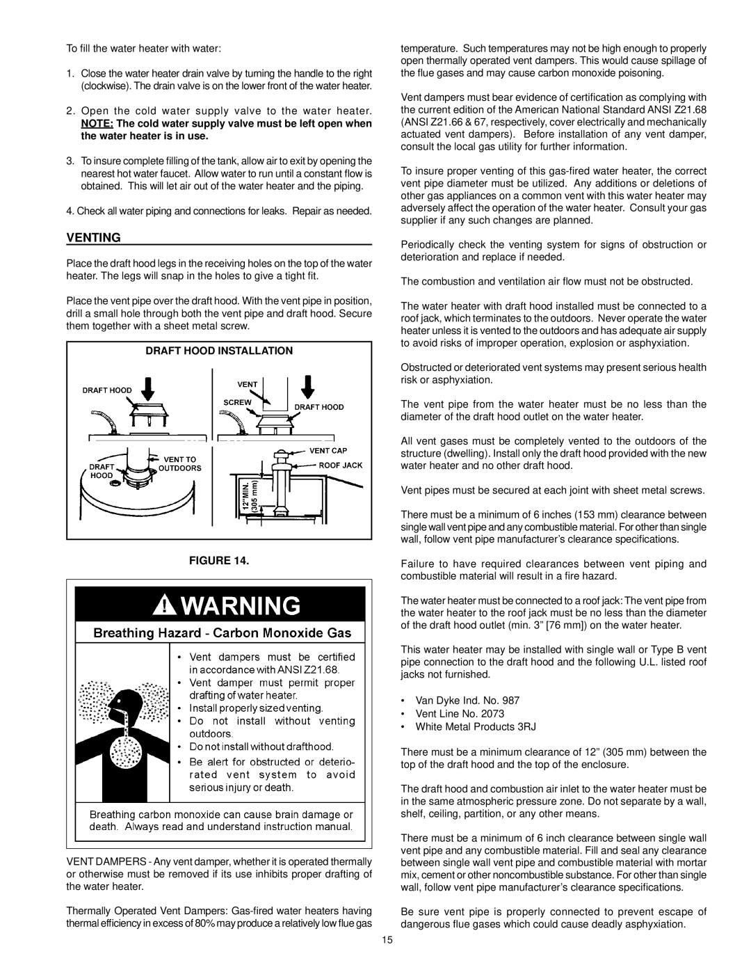
Place the draft hood legs in the receiving holes on the top of the water heater. The legs will snap in the holes to give a tight fit.
Place the vent pipe over the draft hood. With the vent pipe in position, drill a small hole through both the vent pipe and draft hood. Secure them together with a sheet metal screw.
DRAFT HOOD INSTALLATION
FIGURE 14.
VENT DAMPERS - Any vent damper, whether it is operated thermally or otherwise must be removed if its use inhibits proper drafting of the water heater.
Thermally Operated Vent Dampers:
temperature. Such temperatures may not be high enough to properly open thermally operated vent dampers. This would cause spillage of the flue gases and may cause carbon monoxide poisoning.
Vent dampers must bear evidence of certification as complying with the current edition of the American National Standard ANSI Z21.68 (ANSI Z21.66 & 67, respectively, cover electrically and mechanically actuated vent dampers). Before installation of any vent damper, consult the local gas utility for further information.
To insure proper venting of this
Periodically check the venting system for signs of obstruction or deterioration and replace if needed.
The combustion and ventilation air flow must not be obstructed.
The water heater with draft hood installed must be connected to a roof jack, which terminates to the outdoors. Never operate the water heater unless it is vented to the outdoors and has adequate air supply to avoid risks of improper operation, explosion or asphyxiation.
Obstructed or deteriorated vent systems may present serious health risk or asphyxiation.
The vent pipe from the water heater must be no less than the diameter of the draft hood outlet on the water heater.
All vent gases must be completely vented to the outdoors of the structure (dwelling). Install only the draft hood provided with the new water heater and no other draft hood.
Vent pipes must be secured at each joint with sheet metal screws.
There must be a minimum of 6 inches (153 mm) clearance between single wall vent pipe and any combustible material. For other than single wall, follow vent pipe manufacturer’s clearance specifications.
Failure to have required clearances between vent piping and combustible material will result in a fire hazard.
The water heater must be connected to a roof jack: The vent pipe from the water heater to the roof jack must be no less than the diameter of the draft hood outlet (min. 3” [76 mm]) on the water heater.
This water heater may be installed with single wall or Type B vent pipe connection to the draft hood and the following U.L. listed roof jacks not furnished.
•Van Dyke Ind. No. 987
•Vent Line No. 2073
•White Metal Products 3RJ
There must be a minimum clearance of 12” (305 mm) between the top of the draft hood and the top of the enclosure.
The draft hood and combustion air inlet to the water heater must be in the same atmospheric pressure zone. Do not separate by a wall, shelf, ceiling, partition, or any other means.
There must be a minimum of 6 inch clearance between single wall vent pipe and any combustible material. Fill and seal any clearance between single wall vent pipe and combustible material with mortar mix, cement or other noncombustible substance. For other than single wall, follow vent pipe manufacturer’s clearance specifications.
Be sure vent pipe is properly connected to prevent escape of dangerous flue gases which could cause deadly asphyxiation.
15