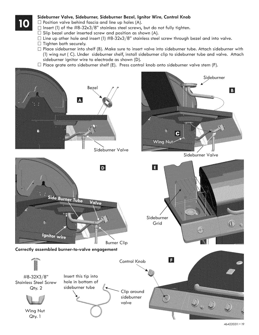
Sideburner Valve, $ideburner Sideburner Bezel, Ignitor Wire, Control Knob [] Position valve behind fascia and line up holes (A).
[] Insert (1) of the
[] Slip bezel under inserted screw and position as shown (A).
[] Line up other hole and insert (1)
[] Tighten both securely.
[] Place sideburner into shelf (B). Make sure to insert valve into sideburner tube. Attach sideburner with
(1)wing nut (C). Under sideburner shelf, install sideburner clip to sideburner tube and valve. Attach sideburner ignitor wire to electrode as shown (D).
[] Place grate onto sideburner shelf (E). Press control knob onto sideburner valve stem (F).
Sideburner
J
Sideburner Valve
Sideburner Valve
Sideburner
|
|
|
|
|
| Grid | |
|
|
|
|
| Burner | Clip | |
Correctly assembled | engagement |
| |||||
|
|
|
|
|
| Control Knob | |
insert | this | tip | into | \\ | |||
Stainless Steel Screw | hole | in bottom | of | ||||
| |||||||
Qty. | 2 |
|
|
| s |
| |
sideburner | tube | around | |||||
|
| ||||||
|
| "x |
| ) | Cl_Pburner | ||
|
|
|
|
|
| valve | |
Wing | Nut |
|
|
|
|
| |
Qty. | 1 |
|
|
|
|
| |
464220311 o 19