Seffing Surface Burner Controls
Seffing the Simmer / Regular / Power / Turbo Boil Burners
Operating the Regular Burner:
oMED
e
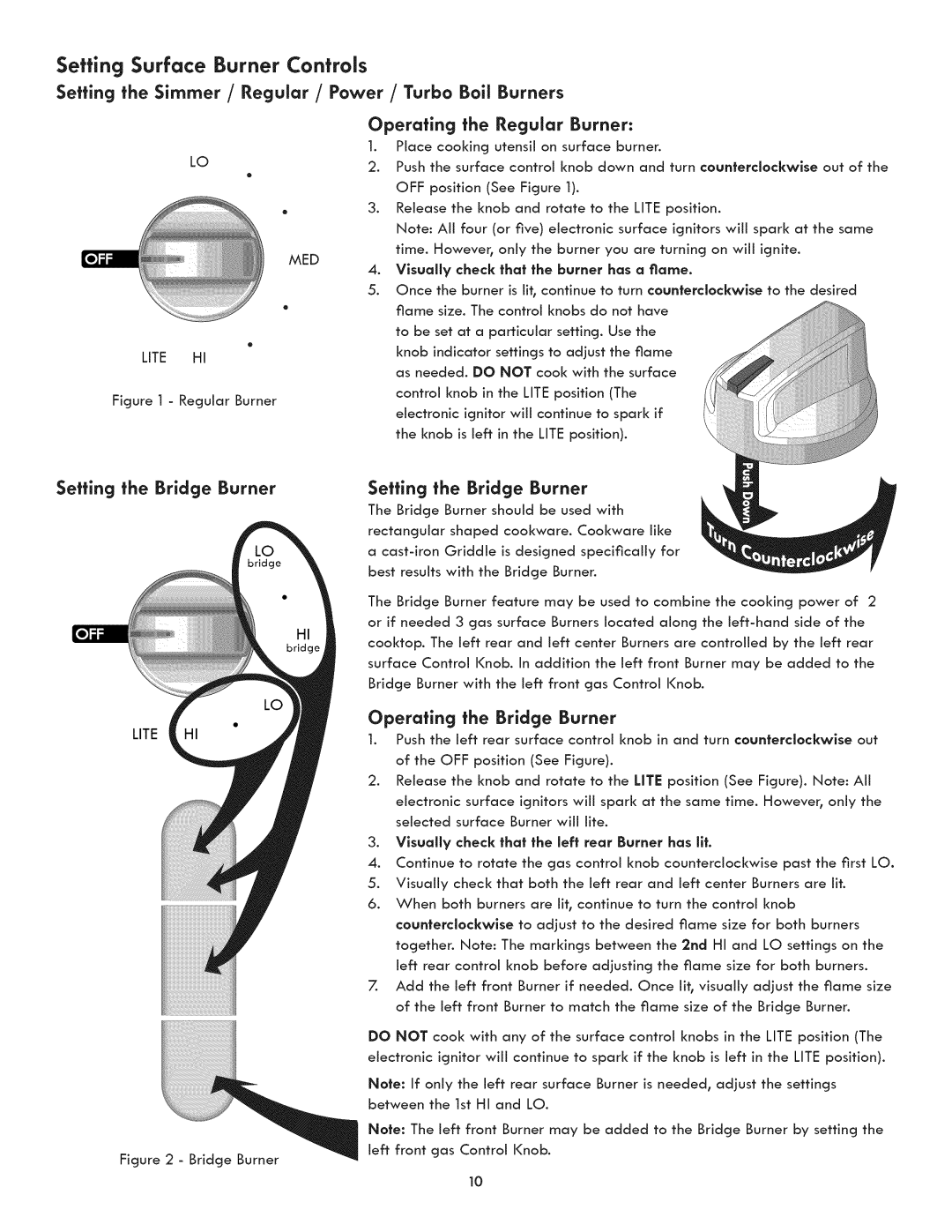
LifE H!
Figure I - Regular Burner
1.Place cooking utensil on surface burner.
2.Push the surface control knob down and turn counferciockwlse out of the OFF position (See Figure 1).
3.Release the knob and rotate to the LImE position.
Note: All four (or five) electronic surface ignitors will spark at the same time. However, only the burner you are turning on will ignite.
4.Vlsua[ly check that the burner has a flame.
5.Once the burner is lit, continue to turn counterclockwise to the desired flame size. The control knobs do not have
to be set at a particular setting. Use the knob indicator settings to adjust the flame as needed. DO NOT cook with the surface
control knob in the LImE position (The electronic ignitor wiJJ continue to spark if
the knob is Jeff in the LImE position).
Seffing the Bridge Burner
LITE
Figure 2 - Bridge Burner
Setting the Bridge Burner
The Bridge Burner should be used with rectangular shaped cookware. Cookware like a
The Bridge Burner feature may be used to combine the cooking power of 2 or if needed 3 gas surface Burners located along the
Operating the Bridge Burner
1.Push the left rear surface control knob in and turn counterclockwise out of the OFF position (See Figure).
2.Release the knob and rotate to the UTE position (See Figure). Note: Aii electronic surface ignitors wiii spark at the same time. However, only the selected surface Burner will life.
3.Vlsua[[y check that the left rear Burner has lit.
4.Continue to rotate the gas control knob counterclockwise past the first LO.
5.Visually check that both the left rear and left center Burners are lit.
6.When both burners are lit, continue to turn the control knob
counterclockwise to adjust to the desired flame size for both burners together. Note: The markings between the 2nd HI and LO settings on the left rear control knob before adjusting the flame size for both burners.
7.Add the left front Burner if needed. Once lit, visually adjust the flame size of the left front Burner to match the flame size of the Bridge Burner.
DO NOT cool< with any of the surface control knobs in the LITE position (The electronic ignitor will continue to spark if the knob is left in the LITE position).
Note: If only the left rear surface Burner is needed, adjust the settings between the 1st HI and LO.
Note: The left front Burner may be added to the Bridge Burner by setting the left front gas Control Knob.
10