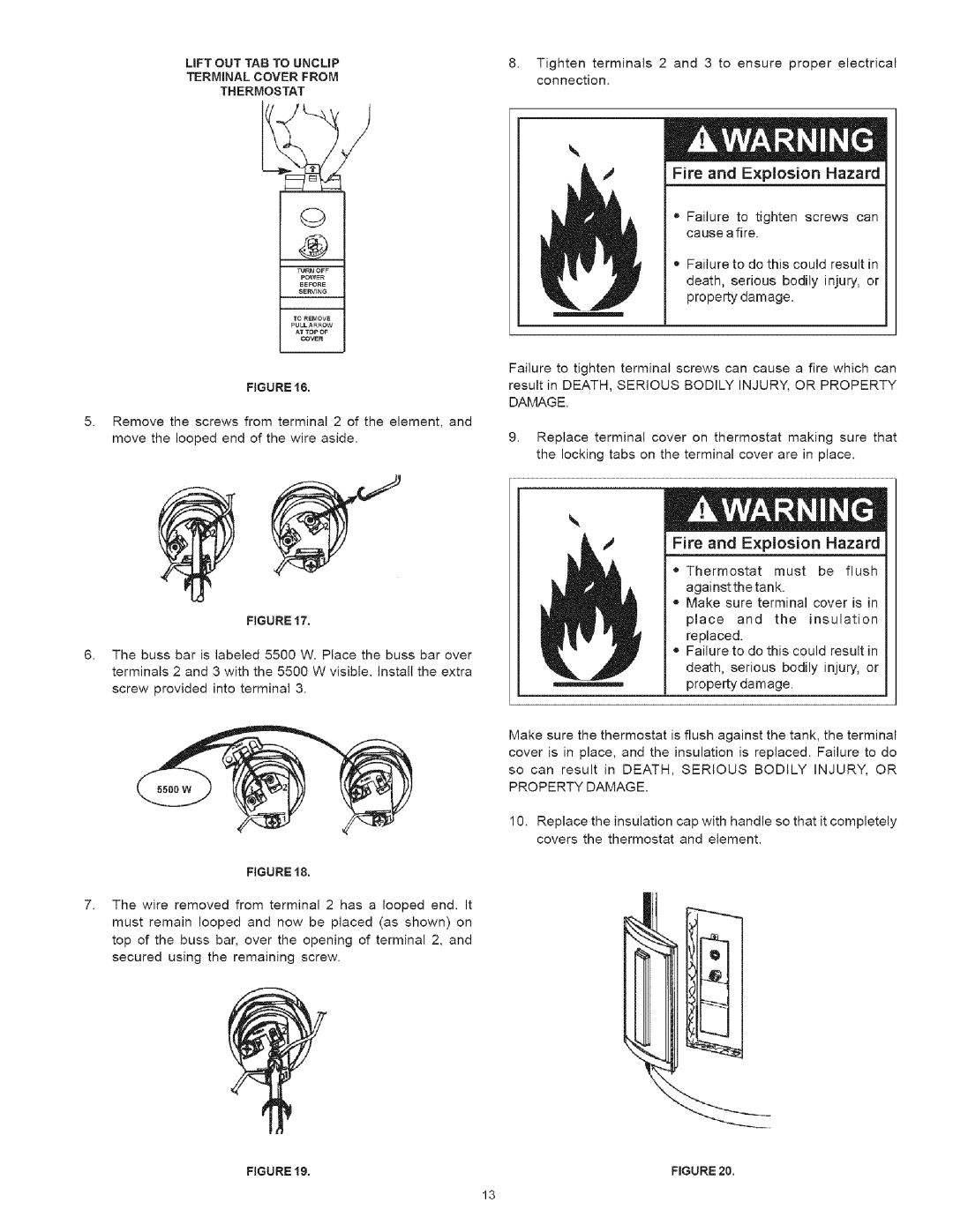
LiFT OUT TAB TO UNCLIP | 8. Tighten terminals 2 and 3 to ensure proper electrical | |
TERMINAL COVER FROM | connection. | |
THERMOSTAT | ||
|
FIGURE 16.
5.Remove the screws from terminal 2 of the element, and move the looped end of the wire aside.
Fire and Explosion Hazard
•Failure to tighten screws can cause a fire.
•Failure to do this could result in death, serious bodily injury, or property damage.
Failure to tighten terminal screws can cause a fire which can result in DEATH, SERIOUS BODILY INJURY, OR PROPERTY DAMAGE.
9.Replace terminal cover on thermostat making sure that the locking tabs on the terminal cover are in place.
FIGURE 17.
6.The buss bar is labeled 5500 W. Place the buss bar over terminals 2 and 3 with the 5500 W visible. Install the extra screw provided into terminal 3.
5500W
FIGURE 18.
7.The wire removed from terminal 2 has a looped end. It must remain looped and now be placed (as shown) on top of the buss bar, over the opening of terminal 2, and secured using the remaining screw.
FIGURE 19.
Fire and E×plosion Hazard
= Thermostat must be flush againstthe tank.
,,Make sure terminal cover is in
place and the insulation
replaced.
e Failure to do this could result in death, serious bodily injury, or property damage.
Make sure the thermostat is flush against the tank, the terminal cover is in place, and the insulation is replaced. Failure to do
so can result in DEATH, SERIOUS BODILY INJURY, OR PROPERTY DAMAGE.
10.Replace the insulation cap with handle so that it completely covers the thermostat and element.
Q
FIGURE 20.
13