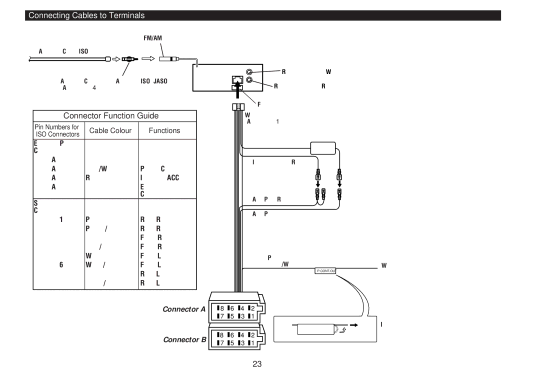
Connecting Cables to Terminals
FM/AM antenna input
Antenna Cord (ISO)
Antenna Conversion Adaptor
Connector Function Guide | ||
Pin Numbers for | Cable Colour | Functions |
ISO Connectors |
|
|
External Power |
|
|
Connector |
|
|
Yellow | Battery | |
Blue/White | Power Control | |
Red | Ignition (ACC) | |
Black | Earth (Ground) | |
|
| Connection |
Speaker |
|
|
Connector |
| Rear Right (+) |
Purple | ||
Purple/Black | Rear Right | |
Gray | Front Right (+) | |
Gray/Black | Front Right | |
White | Front Left (+) | |
White/Black | Front Left | |
Green | Rear Left (+) | |
Green/Black | Rear Left | |
Connector A
Connector B
Rear left output (White)
Rear right output (Red)
Fuse
Wiring harness (Accessory1)
Battery cable (Yellow) ![]()
Ignition cable (Red)
Power control cable (Blue/White)
P.CONT.OUT
|
| 8 |
| 6 |
| 4 |
| 2 |
|
|
|
|
|
|
| ||||
|
| 7 |
| 5 |
| 3 |
| 1 |
|
|
|
|
|
| |||||
|
| 8 |
| 6 |
| 4 |
| 2 |
|
|
|
|
|
| |||||
|
|
|
|
| |||||
|
| 7 |
| 5 |
| 3 |
| 1 |
|
|
|
|
|
| |||||
|
|
|
|
|
When using the optional power amplifier, connect to its power control terminal.
If no connections are made, do not let the cable come out from the tab.
— 23 —