,,)),,..,,,,,...,,,,,.<,,,,,.,,,,~,.,,,,,,,~,,,,..,,,#,.,<,<,,........................ #,#..,,,,,...*,,,...................................... ,,,.",,,.., ,,,, #.,,,,< ,.,,,,,,.#,,,,,.#,,,,..,,,,,,.,,,,%,.,,,,,,.,,,,,,..,,,,.. <,,,,,.,,,,,~cst~.~aa~#~. ..a~a~i. .#,.<.

.-

I ,

--.-',::*

SECTION 7. TROLIBLESHOOTING

i,,,,,..,,,,...,,(,...,,,,,.,,# ,,,.,,,,,,. ",,,,..,,,#.,,,,,..,,,,,,.,,,,,...,,........................ .............................<,%,,,,,,, ..#,,,,,,.#<,,,..,,,,,..,,,,,..,,,,,,.,,,,,,.,S,,,,..,,S,..~,%,,,


..,,,%, ..,,,,#. ,,,,.......................n#ns#nc,~,,,,~,,,, ,,,, ,,,,,, ,,,,, ,,,,,.,,,,#,


7.1

GENERAL INFORMATION

general

b y

improper operation o r connection o f

the trans^


ceivcr,

n o t

b y defcctcve c o m p o n c n t r . Thcrc i s

a reparall:

The

problem5 dercribed i n thir table are f a ~ l u r e caured in

rervice

manual f o r repair o f the TS - 820


7.2TRANSMITTER A N D RECEIVER CIRCUITS

-


SYMPTOMS


CAUSE


R E M E D Y

' Pilot


-


llghrr

d o n o t

light and theye is no

1.

Bad power cahlc or conner!ionr.


1.

Chc?ck col,ll:r

;md connr:riionr

receiver noise when

the POWER r w i l c h i r

2.

B l o w n newer r u p ~ l ylure.


2 .

R ~ p l a cthe~

lure .

turned on.


3.

Wrong

polarily

c o n n r c l i o n

for

D C

3:

Check

for a ncgallvr: ground 0owl:r


operation.


c o n n u c l ~ o n .

Frequency

difference between

transmit

1.

9 V D C supply not aJjurlrd.


1.

See Secl~on6.3.

and

receive.


2.

Short

c l r c u i l in

9 volt powl:r

rut,ply

or

2.

Check

the 9 v o l l i u i i i l l y .


tine.


F M i n g on sideband operation.


3.

Improper battery volkagc in mobile or

3.

Chtcck

h a \ t ~ . r yor altr:rnator volI:lyr:.


portable operation.


V F O lor F I X ) indicator doer

n o t

light.

1.

Rear panel V F O

plug not l n s r r l r d


I 1.

l n l e r t

the jumpered p l u g

The

relays

operate

w i t h

the

stand-by

1.

Improper i n i c r o l ~ h o n rconnccllon .


1.

Requare thc! microphonr: connl~clor .

1w8tch

i n the

R E C position.


-.

Signal

reports

o f o f f

frequency operation

1.

Calibrator requires allgnrnent.


1 .

See Secton 6.3

even though (he dial scale ir calibrated.


7.3 RECEIVER SECTION

SYMPTOMSC A U S E

!

1

!


Accessory CW filter is

installed b u t ielec-

1. Connection of IF board not moved to CW.


l i v i l y and intelligibility

are poor .

2.

Bad CW fllrer.


An antenna i r connecred b u r no signals

1 .

Inoperative V F O or F C orcillalor .


are heard.


2.

Microphone P T T

r w i l c h lor rland - by

-',


switch) is in the transmit posilzon.


3.

Transverter switch

is ON.

-


An antenna is connected and the calibrator

1.

Bad T I R relay.


rignal i s received. b u t no r ~ g n a l are heard.

1 1. See Sectran 6.2

2.Replace the CW filter.

1.Insert Ihe shunt plug into back panel.

2.Release the PTT switch.

-3. Turn tile switch OFF. 1. Replace the relay.

':.

One or m o r e bands are operating b u t rorne

1.

The PLL unit 8s nor operatng on thedefective

arc n o t


band.


2.

The antenna coil o f the defective band


requires alignment.

1 . Repair the PLL unit.

2. See Section 6.3.

1

S-meter deflects w i t h o u t a received signal.

1.

I F

board is our o f

adiurtmenr.


2.

L o w A C line voltage.


1.

I F

board

is & t o f

a d i u r t m r n l ,


2.

R F

gain

control

closed

l o w


senrit;vity.


1. Receiver rectlon reouirer realianmenr.

The R I T control i r

a l zero

w l t h

the R I T

1 .

The R I T

c o n l r o l ,s our o f

adjurtnlenl.

circuit on. b u t the

receive

and

transmit


1 .

R I T circuit o f f .


SSB signal unintelligible.


1 ,

M O D E r w i f c h i r set to wrong rideband,

SSB received slgnal is extremely hlgh cur lor

1


1

IF SHIFT is out of adjustmen?

tow cut/,


1.See Section 6.3

2.Use a s,ep-up transformer to raise the line voltage,

1.See Section

2.Open R F G A I N control.

1.See Section

1.See Seclion

1.Push R I T b u t t o n .

1 . T U , ~M O D E switch to correct ride- band.

1 . se, I ,n the center [in ,he pasilion 01 click)

1

Page 40
Image 40
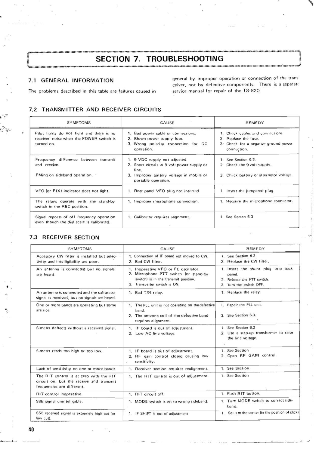
Kenwood TS-820 manual Trolibleshooting, General Information, Transmitter a N D Receiver Circuits, Receiver Section

TS-820 specifications

The Kenwood TS-820 is a high-performance amateur radio transceiver known for its exceptional features and technologies that cater to both novice and experienced operators. This rig, part of Kenwood's renowned TS series, has become a popular choice for those seeking reliability and versatility in their communication equipment.

One of the defining characteristics of the TS-820 is its dual-conversion superheterodyne receiver architecture. This design minimizes interference and provides improved performance across various amateur radio bands. With coverage from 160 meters to 10 meters, the TS-820 is capable of operating on all major HF amateur bands, making it an excellent choice for diverse communication purposes.

In terms of power, the TS-820 delivers a solid output of 100 watts, ensuring that operators can make their presence known across the airwaves. The rig features a built-in automatic antenna tuner, which simplifies the setup process by matching the transmitter to various antenna types. This feature not only enhances signal clarity but also maximizes the station's efficiency.

Another standout feature of the TS-820 is its extensive digital signal processing (DSP) capabilities. The advanced filtering options help to eliminate noise and interference, allowing users to hear weaker signals more clearly and effectively. The IF filter selections can be adjusted to optimize reception under varying conditions, showcasing the rig's adaptability.

The user interface of the TS-820 is designed for both ease of use and functionality. The large, backlit display provides critical information at a glance, while the rotary controls offer tactile feedback, allowing operators to make precise adjustments quickly. Additionally, the rig supports various modes of operation, including SSB, CW, and RTTY, accommodating a wide range of communication preferences.

Built with durability in mind, the TS-820 utilizes high-quality components and construction techniques that ensure long-term reliability. Its rugged design can withstand the rigors of everyday use, making it a trustworthy companion for any amateur radio enthusiast.

In summary, the Kenwood TS-820 is a versatile and reliable amateur radio transceiver that stands out due to its superior performance, advanced technologies, and user-friendly features. With its robust design and comprehensive capabilities, the TS-820 continues to earn its place as a respected choice among ham radio operators around the world. Whether engaged in casual conversation or competitive contesting, enthusiasts can rely on the TS-820 for a satisfying and immersive amateur radio experience.