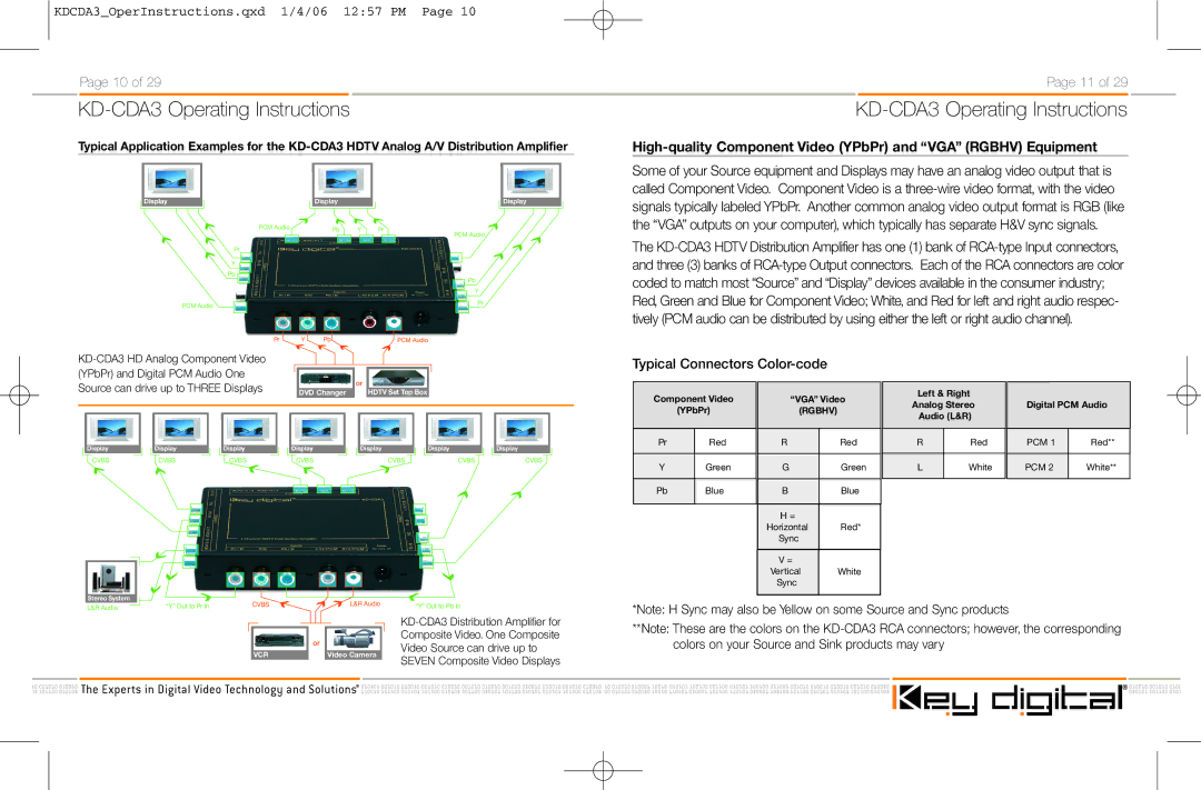
KD-CDA3 specifications
The Key Digital KD-CDA3 is a sophisticated, high-performance audio extractor and distribution amplifier designed to enhance audio fidelity while offering versatile integration capabilities for various AV setups. This device is ideal for businesses, educational institutions, and residential environments where high-quality audio playback is essential.One of the standout features of the KD-CDA3 is its ability to extract audio from HDMI sources, enabling users to separate audio signals for distribution to external audio systems. This capability allows users to enjoy superior sound through dedicated audio equipment without compromising the quality or performance of the HDMI video signal. The KD-CDA3 supports a wide array of audio formats, including PCM, Dolby Digital, and DTS, ensuring compatibility with a variety of audio devices.
In terms of connectivity, the KD-CDA3 features multiple HDMI inputs and outputs, allowing for seamless integration with different devices such as Blu-ray players, gaming consoles, and streaming devices. With its advanced signal processing capabilities, this device ensures low latency, enabling real-time audio playback that is crucial for gaming and live events.
The KD-CDA3 is built with reliability in mind, incorporating robust technologies designed to minimize interference and signal degradation. This allows users to enjoy crystal-clear audio without the distortions often encountered with less advanced devices. Furthermore, the KD-CDA3 includes diverse input options beyond HDMI, such as optical and coaxial inputs, making it compatible with legacy systems and additional audio sources.
Another characteristic that sets the KD-CDA3 apart is its user-friendly interface, featuring easy-to-navigate controls and LED indicators that provide visual feedback on input selection and output status. This interface simplifies the setup process and ensures users can quickly adapt their audio configurations as needed.
Additionally, the Key Digital KD-CDA3 supports both two-channel and multi-channel audio output, making it a versatile tool for various installation scenarios. Its compact design also facilitates easy placement in equipment racks or home theaters. Overall, the KD-CDA3 combines exceptional audio performance, versatile connectivity, and user-friendly features, making it a valuable asset for anyone looking to elevate their audio experience.

