Assembly
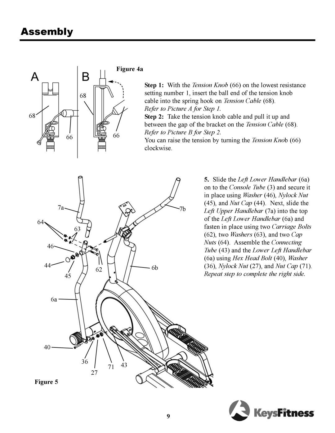
Figure 4a
68
68![]()
6666
Step 1: With the Tension Knob (66) on the lowest resistance setting number 1, insert the ball end of the tension knob cable into the spring hook on Tension Cable (68).
Refer to Picture A for Step 1.
Step 2: Take the tension knob cable and pull it up and between the gap of the bracket on the Tension Cable (68). Refer to Picture B for Step 2.
You can raise the tension by turning the Tension Knob (66) clockwise.
7a
64
46
44![]()
45
6a
40 ![]()
Figure 5
|
|
|
|
|
|
|
|
|
|
|
|
|
|
|
|
| 5. Slide the Left Lower Handlebar (6a) |
|
|
|
|
|
|
|
| on to the Console Tube (3) and secure it |
|
|
|
|
|
|
|
| in place using Washer (46), Nylock Nut |
|
|
|
|
|
|
|
| (45), and Nut Cap (44). Next, slide the |
|
|
|
|
|
| 7b |
| Left Upper Handlebar (7a) into the top |
|
|
|
|
|
|
|
| of the Left Lower Handlebar (6a) and |
|
|
|
|
|
|
|
| fasten in place using two Carriage Bolts |
63 |
|
|
|
|
|
|
| |
|
|
|
|
|
|
| (62), two Washers (63), and two Cap | |
|
|
|
|
|
|
|
| |
|
|
|
|
|
|
|
| Nuts (64). Assemble the Connecting |
|
|
|
|
|
|
|
| Tube (43) and the Lower Left Handlebar |
|
|
|
|
|
|
|
| (6a) using Hex Head Bolt (40), Washer |
|
|
|
|
|
|
| (36), Nylock Nut (27), and Nut Cap (71). | |
|
|
| 6b | |||||
62 | ||||||||
|
|
|
|
|
|
|
| Repeat step to complete the right side. |
|
|
|
|
|
|
|
| |
|
|
|
|
|
|
|
| |
|
|
|
|
|
|
|
|
|
36 | 43 |
71 | |
27 |
|
9
