COMPVT65 SUBWOOFER Owner’s Manual
Models: CompVT65
Authorized KICKER Dealer:
Purchase Date:
Speaker Model Number:
Speaker Serial Number:
Kicker CompVT 65 subwoofers were specially designed for “Livin’ Loud” in the harsh automotive environment. CompVT subwoofers are versatile and surpass the competition in a sealed box, but can also be mounted in free air applications and factory cutout locations. The small diameter of the CompVT 65 subwoofers make them ideal for custom installations and
SPECIFICATIONS
Model | CompVT65 |
Nominal Impedance [Zn], ohm [per coil] | 2 or 4 |
Resonance Frequency [fs], Hz | 53.9 |
Power Handling Watts, Peak (RMS) | 300 (150) |
Sensitivity [SPLo], dB @ 1W, 1m | 84.6 |
Total | .667 |
Mechanical | 9.426 |
Electrical | .718 |
Effective Excursion [EXmax™], in. (mm) | .17 (4.3) |
DC Resistance [Re], ohm | 2.05 |
Equivalent Volume [Vas], ft3 (L) | .328 (9.28) |
Net Displacement, in3 (cc) | 21 (344) |
Outer Frame Dimension, in (cm) | |
Mounting Depth, in (cm) | |
Hole |
Note: All specifi cations and performance fi gures are subject to change. Please visit www.kicker.com for the most current information. To get the best performance from your new KICKER Subwoofer, we recommend using genuine KICKER Accessories and Wiring. Please allow two weeks of
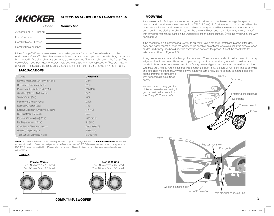
MOUNTING
If you are replacing factory speakers in their original locations, you may have to enlarge the speaker
If the speaker
It may be necessary to run wire through the door jamb. The speaker wire should be kept away from sharp edges and avoid the possibility of getting pinched by the door. An existing grommet in the door jamb is the ideal place to run the speaker wire. If the factory hole and grommet do not exist or are inaccessible, you must drill a hole to run the speaker wire through the door jamb. Be careful not to drill into other wiring or exiting door mechanisms. Any time a wire is run through a hole, it is necessary to insert a rubber or plastic grommet to protect the
wire from damage as outlined below.
We recommend using genuine Kicker accessories and wiring to get the best performance from your CompVT 65 subwoofer.
CompVT
Figure 3
Rubber grommets
performance.
WIRING
| Figure 1 |
Parallel Wiring | Series Wiring |
Two 2Ω Woofers = 1Ω Load | Two 2Ω Woofers = 4Ω Load |
Two 4Ω Woofers = 2Ω Load | Two 4Ω Woofers = 8Ω Load |
2COMPVT65SUBWOOFER
2010 CompVT 65 c01.indd
Woofer mounting hole
To woofer terminals
Door jamb
From amplifi er or source unit
3
9/18/2009 10:16:22 AM