SEALED ENCLOSURE APPLICATIONS
The CompVT generates more sound pressure than competing subwoofers on the market and excels when used in the recommended sealed boxes. These sealed enclosure designs give the smoothest response with increased energy at the lowest frequencies. These designs deliver massive amounts of
Panel Dimensions for Compact Sealed Enclosures using 3/4” (1.9cm) thick MDF (See Figure 4)
Figure 5
Model | Volume ft3 (L) | Panel A in. (cm) | Panel B in. (cm) | Panel C in. (cm) |
CompVT65 | .2 ft3 (5.66L) | 14x14 (35.6x35.6) | 14x2 (35.6x5.1) | 12.5x2 (31.8x5.1) |
Sealed Compact |
|
|
| Sealed SQ |
|
|
Model | Volume ft3 (L) | Power Handling |
| Model | Volume ft3 (L) | Power Handling |
|
|
|
|
|
|
|
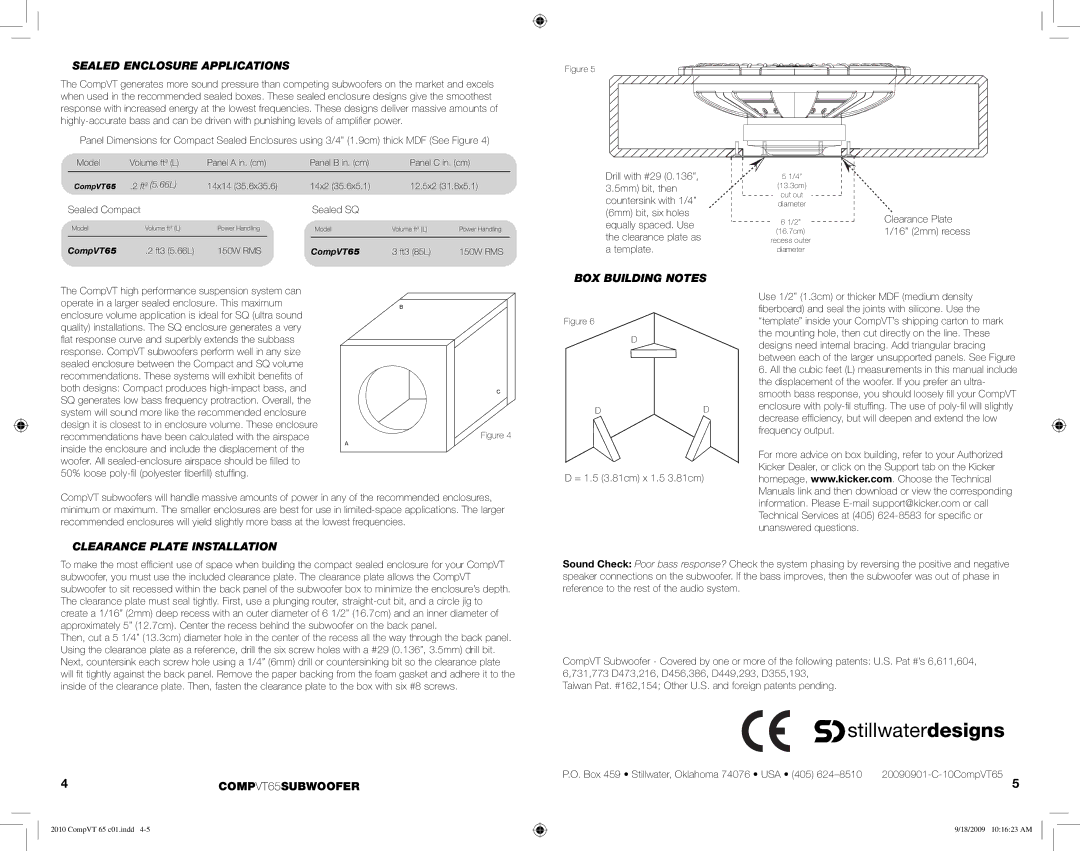
Drill with #29 (0.136”, 3.5mm) bit, then countersink with 1/4” (6mm) bit, six holes equally spaced. Use the clearance plate as
51/4”
(13.3cm)
cut out
diameter
6 1/2”
(16.7cm)
recess outer
Clearance Plate 1/16” (2mm) recess
CompVT65 | .2 ft3 (5.66L) | 150W RMS | CompVT65 |
3 ft3 (85L) | 150W RMS |
a template.
diameter
The CompVT high performance suspension system can operate in a larger sealed enclosure. This maximum enclosure volume application is ideal for SQ (ultra sound quality) installations. The SQ enclosure generates a very
flat response curve and superbly extends the subbass response. CompVT subwoofers perform well in any size sealed enclosure between the Compact and SQ volume recommendations. These systems will exhibit benefi ts of both designs: Compact produces
B |
C
Figure 4
BOX BUILDING NOTES
Figure 6
D
DD
Use 1/2” (1.3cm) or thicker MDF (medium density
fiberboard) and seal the joints with silicone. Use the “template” inside your CompVT’s shipping carton to mark the mounting hole, then cut directly on the line. These designs need internal bracing. Add triangular bracing between each of the larger unsupported panels. See Figure 6. All the cubic feet (L) measurements in this manual include the displacement of the woofer. If you prefer an ultra- smooth bass response, you should loosely fi ll your CompVT enclosure with
inside the enclosure and include the displacement of the woofer. All
A
D = 1.5 (3.81cm) x 1.5 3.81cm)
For more advice on box building, refer to your Authorized Kicker Dealer, or click on the Support tab on the Kicker homepage, www.kicker.com. Choose the Technical Manuals link and then download or view the corresponding
CompVT subwoofers will handle massive amounts of power in any of the recommended enclosures, minimum or maximum. The smaller enclosures are best for use in
CLEARANCE PLATE INSTALLATION
To make the most effi cient use of space when building the compact sealed enclosure for your CompVT subwoofer, you must use the included clearance plate. The clearance plate allows the CompVT subwoofer to sit recessed within the back panel of the subwoofer box to minimize the enclosure’s depth. The clearance plate must seal tightly. First, use a plunging router,
Then, cut a 5 1/4” (13.3cm) diameter hole in the center of the recess all the way through the back panel. Using the clearance plate as a reference, drill the six screw holes with a #29 (0.136”, 3.5mm) drill bit. Next, countersink each screw hole using a 1/4” (6mm) drill or countersinking bit so the clearance plate will fi t tightly against the back panel. Remove the paper backing from the foam gasket and adhere it to the inside of the clearance plate. Then, fasten the clearance plate to the box with six #8 screws.
4COMPVT65SUBWOOFER
2010 CompVT 65 c01.indd
information. Please
Sound Check: Poor bass response? Check the system phasing by reversing the positive and negative speaker connections on the subwoofer. If the bass improves, then the subwoofer was out of phase in reference to the rest of the audio system.
CompVT Subwoofer - Covered by one or more of the following patents: U.S. Pat #’s 6,611,604, 6,731,773 D473,216, D456,386, D449,293, D355,193,
Taiwan Pat. #162,154; Other U.S. and foreign patents pending.
 stillwaterdesigns
P.O. Box 459 • Stillwater, Oklahoma 74076 • USA • (405) | |
| 5 |
| 9/18/2009 10:16:23 AM |
