
IX500.4 specifications
The Kicker IX500.4 is an innovative car amplifier that stands out in the competitive audio marketplace for its superior engineering and performance. It is a four-channel amplifier that packs a punch, delivering powerful audio output to enhance the listening experience in any vehicle.One of the key features of the IX500.4 is its impressive power output. With a maximum output of 500 watts, this amplifier provides strong performance, making it an ideal choice for car audio enthusiasts looking to upgrade their sound systems. It produces a continuous output of 75 watts per channel at 4 ohms and 100 watts at 2 ohms, ensuring that every note and beat comes through with clarity and impact.
The IX500.4 is equipped with advanced technology that enhances its performance. It features Kicker’s exclusive "Smart Start" technology, which allows for faster power-up times and ensures that the amplifier is always ready to deliver its full potential. This means that users can enjoy a reliable audio experience without any interruptions, even during extended listening sessions.
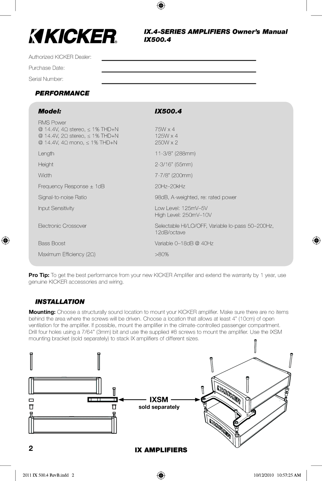
Another notable characteristic of the IX500.4 is its compact and lightweight design. This allows for easy installation in a wide range of vehicles, making it an excellent option for those with limited space. Additionally, the amplifier's rugged construction ensures durability, so users can enjoy their music worry-free.
The amplifier includes variable crossovers, allowing users to customize the sound to their preferences. With both high and low-pass settings, this feature enables audiophiles to fine-tune the audio frequencies, leading to a personalized listening experience. Furthermore, it is equipped with a built-in, thermal and short-circuit protection system, which safeguards the amplifier from damage, ensuring longevity.
Overall, the Kicker IX500.4 is a powerful, versatile amplifier that combines cutting-edge technology with a user-friendly design. Its ability to deliver impressive sound quality while offering customization options makes it a top choice for anyone looking to elevate their car audio system. Whether you're a casual listener or a serious audiophile, the IX500.4 is designed to meet the demands of modern audio playback, enhancing your journey with every drive.