System Diagrams
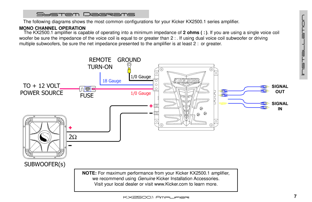
The following diagrams shows the most common configurations for your Kicker KX2500.1 series amplifier.
MONO CHANNEL OPERATION
The KX2500.1 amplifier is capable of operating into a minimum impedance of 2 ohms (Ω). If you are using a single voice coil woofer be sure the impedance of the voice coil is equal to or greater than 2Ω. If using dual voice coil subwoofer or driving multiple subwoofers, be sure the net impedance presented to the amplifier is at least 2Ω or greater.
REMOTE GROUND
Installation
TO + 12 VOLT | KICKER | |
POWER SOURCE | 300 A | |
FUSE | ||
|
1/0 Gauge
18 Gauge
| SIGNAL | |
1/0 Gauge | OUT | |
| ||
+ | SIGNAL | |
IN | ||
|
+
2Ω
SUBWOOFER(s)
NOTE: For maximum performance from your Kicker KX2500.1 amplifier,
we recommend using Genuine Kicker Installation Accessories. Visit your local dealer or visit www.Kicker.com to learn more.
KX2500.1 Amplifier | 7 |