Operation
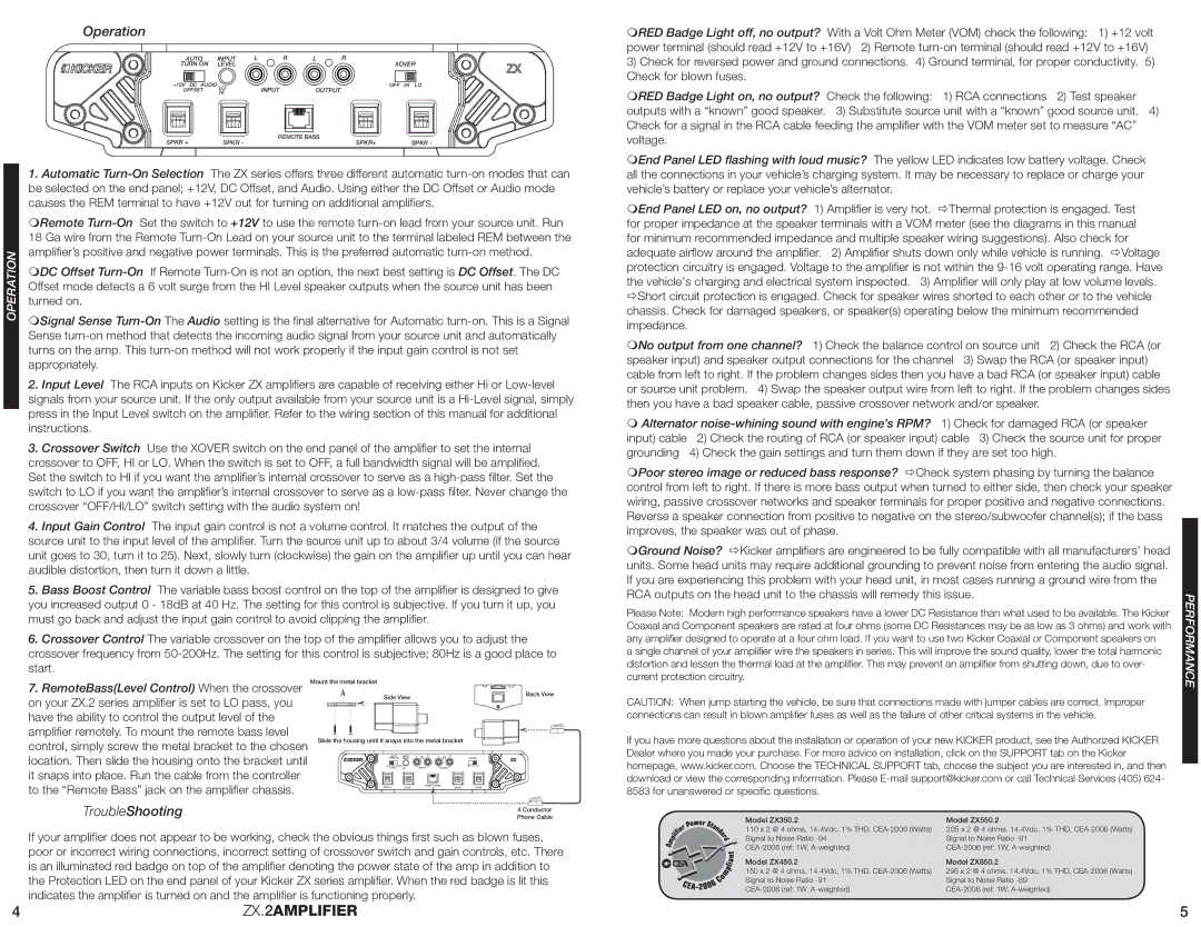
AUTO | INPUT | L | R | L | R | |
TURN ON | LEVEL | | | | XOVER |
+12V DC AUDIO LO | | INPUT | | OFF | HI LO |
OFFSET | HI | | OUTPUT | | |
SPKR + | SPKR - | | REMOTE BASS | SPKR+ | SPKR - |
| | |
1.Automatic Turn-On Selection The ZX series offers three different automatic turn-on modes that can be selected on the end panel; +12V, DC Offset, and Audio. Using either the DC Offset or Audio mode causes the REM terminal to have +12V out for turning on additional amplifiers.
Remote Turn-OnSet the switch to +12V to use the remote turn-on lead from your source unit. Run 18 Ga wire from the Remote Turn-On Lead on your source unit to the terminal labeled REM between the amplifier’s positive and negative power terminals. This is the preferred automatic turn-on method.
DC Offset Turn-OnIf Remote Turn-On is not an option, the next best setting is DC Offset. The DC Offset mode detects a 6 volt surge from the HI Level speaker outputs when the source unit has been turned on.
Signal Sense Turn-OnThe Audio setting is the final alternative for Automatic turn-on. This is a Signal Sense turn-on method that detects the incoming audio signal from your source unit and automatically turns on the amp. This turn-on method will not work properly if the input gain control is not set appropriately.
2.Input Level The RCA inputs on Kicker ZX amplifiers are capable of receiving either Hi or Low-level signals from your source unit. If the only output available from your source unit is a Hi-Level signal, simply press in the Input Level switch on the amplifier. Refer to the wiring section of this manual for additional instructions.
3.Crossover Switch Use the XOVER switch on the end panel of the amplifier to set the internal crossover to OFF, HI or LO. When the switch is set to OFF, a full bandwidth signal will be amplified. Set the switch to HI if you want the amplifier’s internal crossover to serve as a high-pass filter. Set the switch to LO if you want the amplifier’s internal crossover to serve as a low-pass filter. Never change the crossover “OFF/HI/LO” switch setting with the audio system on!
4.Input Gain Control The input gain control is not a volume control. It matches the output of the source unit to the input level of the amplifier. Turn the source unit up to about 3/4 volume (if the source unit goes to 30, turn it to 25). Next, slowly turn (clockwise) the gain on the amplifier up until you can hear audible distortion, then turn it down a little.
5.Bass Boost Control The variable bass boost control on the top of the amplifier is designed to give you increased output 0 - 18dB at 40 Hz. The setting for this control is subjective. If you turn it up, you must go back and adjust the input gain control to avoid clipping the amplifier.
6.Crossover Control The variable crossover on the top of the amplifier allows you to adjust the crossover frequency from 50-200Hz. The setting for this control is subjective; 80Hz is a good place to start.
RED Badge Light off, no output? With a Volt Ohm Meter (VOM) check the following: 1) +12 volt power terminal (should read +12V to +16V) 2) Remote turn-on terminal (should read +12V to +16V)
3)Check for reversed power and ground connections. 4) Ground terminal, for proper conductivity. 5) Check for blown fuses.
RED Badge Light on, no output? Check the following: 1) RCA connections 2) Test speaker outputs with a “known” good speaker. 3) Substitute source unit with a “known” good source unit. 4) Check for a signal in the RCA cable feeding the amplifier with the VOM meter set to measure “AC” voltage.
End Panel LED flashing with loud music? The yellow LED indicates low battery voltage. Check all the connections in your vehicle’s charging system. It may be necessary to replace or charge your vehicle’s battery or replace your vehicle’s alternator.
End Panel LED on, no output? 1) Amplifier is very hot. Thermal protection is engaged. Test for proper impedance at the speaker terminals with a VOM meter (see the diagrams in this manual for minimum recommended impedance and multiple speaker wiring suggestions). Also check for adequate airflow around the amplifier. 2) Amplifier shuts down only while vehicle is running. Voltage protection circuitry is engaged. Voltage to the amplifier is not within the 9-16 volt operating range. Have the vehicle's charging and electrical system inspected. 3) Amplifier will only play at low volume levels. Short circuit protection is engaged. Check for speaker wires shorted to each other or to the vehicle chassis. Check for damaged speakers, or speaker(s) operating below the minimum recommended impedance.
No output from one channel? 1) Check the balance control on source unit 2) Check the RCA (or speaker input) and speaker output connections for the channel 3) Swap the RCA (or speaker input) cable from left to right. If the problem changes sides then you have a bad RCA (or speaker input) cable or source unit problem. 4) Swap the speaker output wire from left to right. If the problem changes sides then you have a bad speaker cable, passive crossover network and/or speaker.
Alternator noise-whining sound with engine’s RPM? 1) Check for damaged RCA (or speaker
input) cable | 2) Check the routing of RCA (or speaker input) cable 3) Check the source unit for proper |
grounding | 4) Check the gain settings and turn them down if they are set too high. |
Poor stereo image or reduced bass response? Check system phasing by turning the balance control from left to right. If there is more bass output when turned to either side, then check your speaker wiring, passive crossover networks and speaker terminals for proper positive and negative connections. Reverse a speaker connection from positive to negative on the stereo/subwoofer channel(s); if the bass improves, the speaker was out of phase.
Ground Noise? Kicker amplifiers are engineered to be fully compatible with all manufacturers’ head units. Some head units may require additional grounding to prevent noise from entering the audio signal. If you are experiencing this problem with your head unit, in most cases running a ground wire from the RCA outputs on the head unit to the chassis will remedy this issue.
Please Note: Modern high performance speakers have a lower DC Resistance than what used to be available. The Kicker Coaxial and Component speakers are rated at four ohms (some DC Resistances may be as low as 3 ohms) and work with any amplifier designed to operate at a four ohm load. If you want to use two Kicker Coaxial or Component speakers on
a single channel of your amplifier wire the speakers in series. This will improve the sound quality, lower the total harmonic distortion and lessen the thermal load at the amplifier. This may prevent an amplifier from shutting down, due to over- current protection circuitry.