Before you start...
Fire Hazard
For your safety the information in this manual must be followed to minimize the risk of fire or explosion or to prevent property damage, personal injury or loss of life.
-Do Not store or use gasoline or other flammable vapors and liquids in the vicinity of this or any other appliance.
-WHAT TO DO IF YOU SMELL GAS
l Do Not try to light any appliance.
l Do Not touch any electrical switch; Do Not use any phone in your building.
l Clear the room, building or area of all occupants.
l Immediately call your gas supplier from a neighbor’s phone. Follow the gas supplier’s instructions.
l If you cannot reach your gas supplier, call the fire department.
-Never install dryer up against draperies or curtains or on carpet.
-Keep any and all items from falling or collecting behind the dryer.
Installation and service must be performed by a qualified installer, service agency or the gas supplier.
l Size: Must be large enough to fully open dyer door. For recessed or closet installation spacing, see back cover.
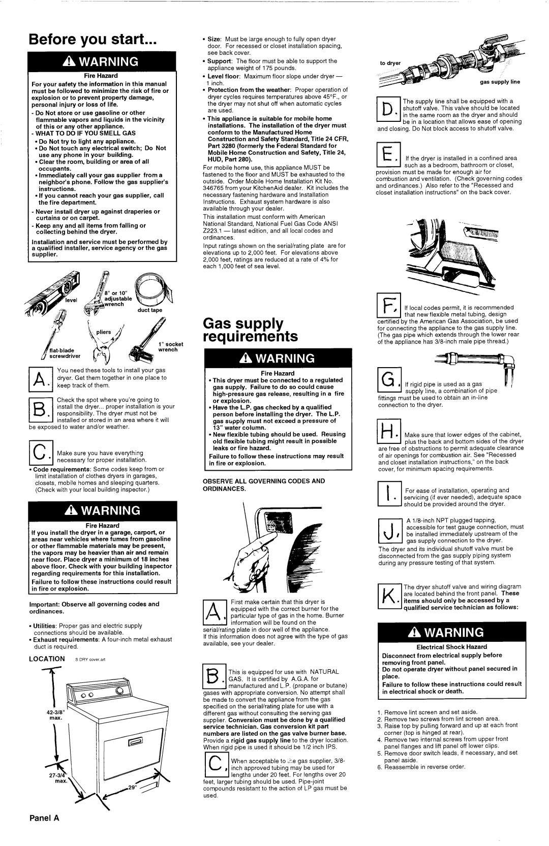
l Support: The floor must be able to support the appliance weight of 175 pounds.
l Level floor: Maximum floor slope under dryer - 1 inch.
l Protection from the weather: Proper operation of dryer cycles requires temperatures above 45”F., or the dyer may not shut off when automatic cycles are used.
l This appliance is suitable for mobile home installations. The installation of the dryer must conform to the Manufactured Home Construction and Safety Standard, Title 24 CFR, Part 3280 (formerly the Federal Standard for Mobile Home Construction and Safety, Title 24, HUD, Part 280).
For mobile home use, this appliance MUST be fastened to the floor and MUST be exhausted to the outside. Order Mobile Home Installation Kit No. 346765 from your KitchenAid dealer. Kit includes the necessary fastening hardware and Installation Instructions. Exhaust system hardware is also available through your dealer.
This installation must conform with American National Standard, National Fuel Gas Code ANSI 2223.1 - latest edition, and all local codes and ordinances.
Input ratings shown on the serial/rating plate are for elevations up to 2,000 feet. For elevations above 2,000 feet, ratings are reduced at a rate of 4% for each 1,000 feet of sea level.
D The supply line shall be equipped with a 17shutoff valve. This valve should be located
* in the same room as the dryer and should be in a location that allows ease of opening
and closing. Do Not block access to shutoff valve.
0ELIf the dryer is installed in a confined area such as a bedroom, bathroom or closet,
provision must be made for enough air for combustion and ventilation. (Check governing codes and ordinances.) Also refer to the “Recessed and closet installation instructions” on the back cover.
IFI, If local codes permit, it is recommended that new flexible metal tubing, design
You need these tools to install your gas dyer. Get them together in one place to keep track of them.
Check the spot where you’re going to install the dyer... proper installation is your responsibility. The dyer must not be installed or stored in an area where it will
be exposed to water and/or weather.
I | 1 |
IcI | Make sure you have everything | |
l II necessarv I | for IInrooer installation. | |
l Code | requirements: | Some codes keep from or |
limit installation of clothes dyers in garages, closets, mobile homes and sleeping quarters. (Check with your local building inspector.)
Fire Hazard
If you install the dryer in a garage, carport, or areas near vehicles where fumes from gasoline or other flammable materials may be present, the vapors may be heavier than air and remain near floor. Place dryer a minimum of 18 inches above floor. Check with your building inspector
regarding | requirements | for this installation. | |
Failure to | follow these | instructions | could result |
I in fire or | explosion. |
| I |
Important: Observe all governing codes and ordinances.
l Utilities: Proper gas and electric supply connections should be available.
l Exhaust requirements: A
LOCATION S DRY co”er.arl
Gas supply requirements
Fire Hazard
l This dryer must be connected to a regulated gas supply. Failure to do so could cause
l Have the L.P. gas checked by a qualified person before installing the dryer. The L.P. gas supply must not exceed a pressure of 13” water column.
l New flexible tubing should be used. Reusing old flexible tubing might result in possible leaks or fire hazard.
Failure to follow these instructions may result in fire or explosion.
OBSERVE ALL GOVERNING CODES AND ORDINANCES.
ElFirst make certain that this dryer is equipped with the correct burner for the
, particular type of gas in the home. Burner information will be found on the
serial/rating plate in door well of the appliance.
If this information does not agree with the type of gas available, see your dealer.
0This is equipped for use with NATURAL GAS. It is certified by A.G.A. for
*manufactured and L.P. (propane or butane) gases with appropriate conversion. No attempt shall be made to convert the appliance from the gas specified on the serial/rating plate for use with a different gas without consulting the serving gas supplier. Conversion must be done by a qualified service technician. Gas conversion kit part numbers are listed on the gas valve burner base.
Provide a rigid gas supply line to the dryer location. When rigid pipe is used it should be l/2 inch IPS.13
C When acceptable to ,?,e gas supplier,
0lengths under 20 feet. For lengths over 20 feet, larger tubing should be used.
certified by the American Gas Association, be used for connecting the appliance to the gas supply line. (The gas pipe which extends through the lower rear of the appliance has
If rigid pipe is used as a gas supply line, a combination of pipe
fittings must be used to obtain an
Els Make sure that lower edges of the cabinet, plus the back and bottom sides of the dyer are free of obstructions to permit adequate clearance
of air openings for combustion air. See “Recessed and closet installation instructions,” on the back cover, for minimum spacing requirements.
h
. servicing (if ever needed), adequate space should be provided around the dyer.
A
I accessible for test gauge connection, must IJ be installed immediately upstream of the
gas supply connection to the dryer.
The dyer and its individual shutoff valve must be disconnected from the gas supply piping system during any pressure testing of that system.
7 The dyer shutoff valve and wiring diagram K are located behind the front panel. These
. items should only be accessed by a qualified service technician as follows:
Electrical Shock Hazard
Disconnect from electrical supply before removing front panel.
Do not operate dryer without panel secured in place.
Failure to follow these instructions could result in electrical shock or death.
1.Remove lint screen and set aside.
2.Remove two screws from lint screen area.
3.Raise top by pulling forward and up at each front corner (top is hinged at rear).
4.Remove two internal screws from upper front panel flanges and lift panel off lower clips.
5.Remove door switch leads, if necessary, and set panel aside.
6.Reassemble in reverse order.
Panel A