2. 3.
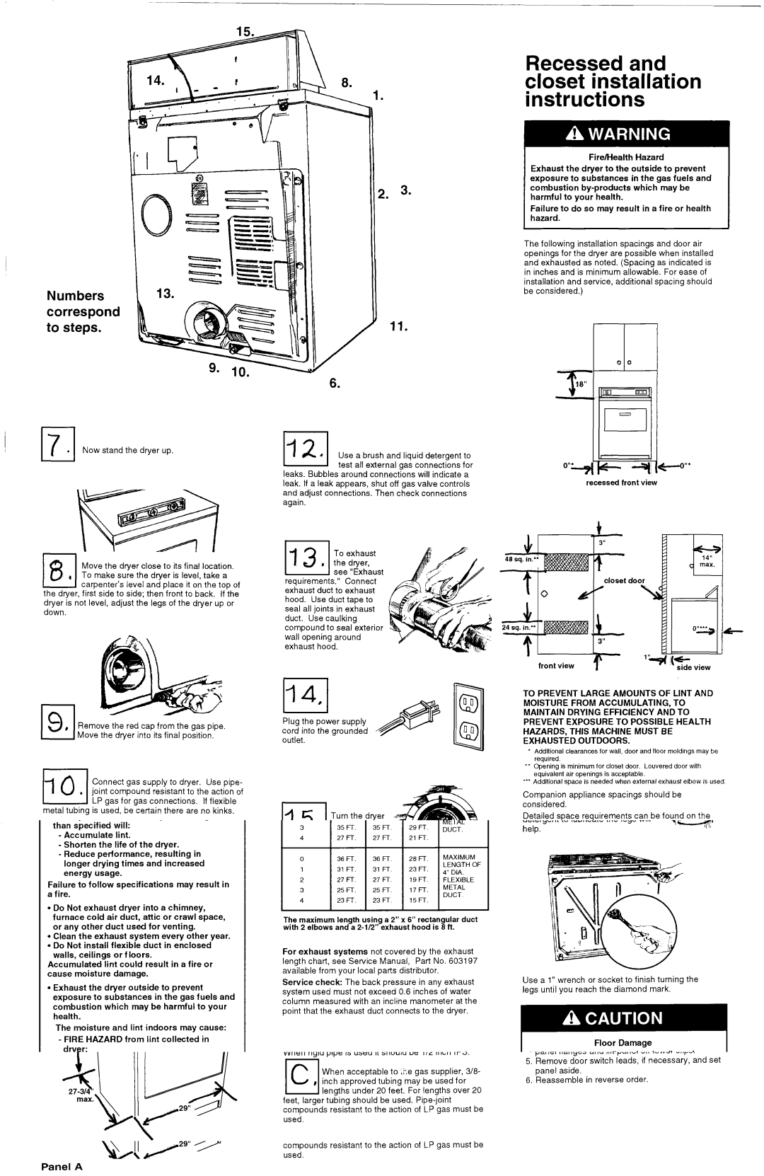
Recessed and closet installation instructions
Fire/Health Hazard
Exhaust the dryer to the outside to prevent exposure to substances in the gas fuels and combustion
Failure to do so may result in a fire or health hazard.
Numbers correspond to steps.
.
17Now stand the dryer up.
1 1
carpenter’s level and place it on the top of the dryer, first side to side; then front to back. If the dryer is not level, adjust the legs of the dryer up or down.
Remove the red cap from the gas pipe.
Move the dryer into its final position.
I | I |
|
|
|
I | Connect gas supply to dryer. Use pipe- | |||
. joint compound | resistant | to the action of | ||
LP gas for gas | connections. | If flexible | ||
metal tubing is used, be certain there | are | no kinks. | ||
Open the shutoff valve in the gas supply line.
Fire Hazard
Do Not use an open flame to test for leaks from gas connections.
Checking for leaks with a flame may result in a fire or explosion.
/
6.
-test all external gas connections for leaks. Bubbles around connections will indicate a leak. If a leak appears, shut off gas valve controls and adjust connections. Then check connections again.
To exhaust the dryer, see “Exhaust
requirements.” Connect exhaust duct to exhaust hood. Use duct tape to seal all joints in exhaust duct. Use caulking compound to seal exterior wall opening around exhaust hood.
Plug the power supply cord into the grounded outlet.
Turn the dryer on to remove air from the gas
supply line. Using a full heat cycle (not the air cycle), let the dryer run for at least five minutes. If the burner does not ignite and you can feel no heat inside the dryer, shut
off the dryer for five minutes. timer c~ntrct knob Check that the gas supply line
shutoff valve is in “ON”position. Repeat the five- minute test.
Check to make sure you have all the tools you started with in Step A,
To get the most efficient use from your new dryer, read your KitchenAid Use and Care Guide. Keep Installation Instructions and Guide close to dryer for easy reference.
The following installation spacings and door air openings for the dryer are possible when installed and exhausted as noted. (Spacing as indicated is in inches and is minimum allowable. For ease of installation and service, additional spacing should be considered.)
recessed front view
I IM I
da
TO PREVENT LARGE AMOUNTS OF LINT AND MOISTURE FROM ACCUMULATING, TO MAINTAIN DRYING EFFICIENCY AND TO PREVENT EXPOSURE TO POSSIBLE HEALTH HAZARDS, THIS MACHINE MUST BE EXHAUSTED OUTDOORS.
+Additional clearances for wall, door and floor moldings may be required.
--Opening is minimum for close1 door. Louvered door with equivalent air openings is acceptable.
-Additional space is needed when external exhaust elbow is used
Companion appliance spacings should be considered.
Detailed space requirements can be found on the label located on the back panel of dryer.
NOTE: No other
Part No. 3395322 Rev. A
Panel C