Attachment
l/8" |
|
|
|
|
top | ; | ; | ; |
|
bracket |
| |||
to ceiling | 1 |
| I |
|
| I |
| I |
|
| I |
| I |
|
| I |
| I | middle |
| I |
|
| |
| I | I | : | bracket |
| +z& |
|
| |
| I | ’ | I |
|
| I |
| I |
|
| I |
| I |
|
| I |
| I |
|
| I |
| I |
|
I
I
24” min.
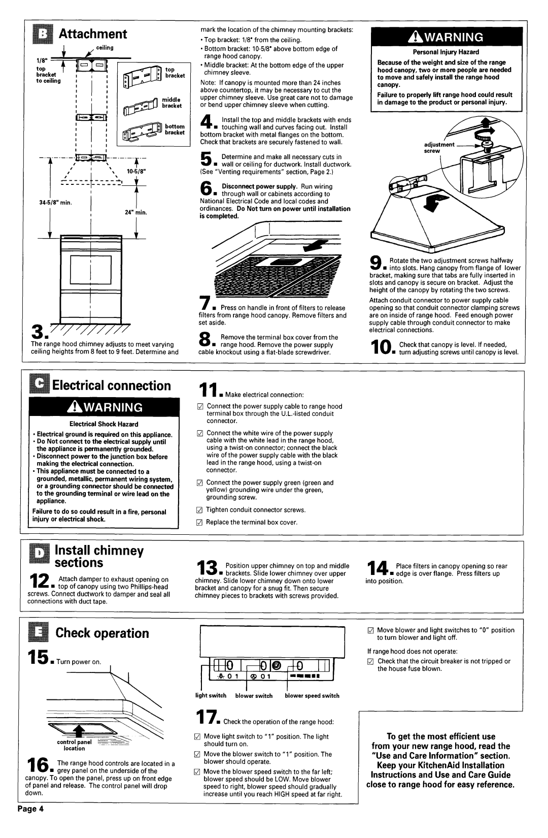
mark the location of the chimney mounting brackets:
l Top bracket: l/8’ from the ceiling.
l Bottom bracket:
l Middle bracket: At the bottom edge of the upper chimney sleeve.
Note: If canopy is mounted more than 24 inches above countertop, it may be necessary to cut the upper chimney sleeve. Use great care not to damage or bend upper chimney sleeve when cutting.
4 Install the top and middle brackets with ends n touching wall and curves facing out. Install
bottom bracket with metal flanges on the bottom. Check that brackets are securely fastened to wall.
5 Determine and make all necessary cuts in
n wall or ceiling for ductwork. Install ductwork. (See “Venting requirements” section, Page 2.)
6 Disconnect power supply. Run wiring n through wall or cabinets according to National Electrical Code and local codes and
ordinances. Do Not turn on power until installation is completed.
AI
Personal Injury Hazard
Because of the weight and size of the range hood canopy, two or more people are needed to move and safely install the range hood canopy.
Failure to properly lift range hood could result in damage to the product or personal injury.
9 Rotate the two adjustment screws halfway
n into slots. Hang canopy from flange of lower bracket, making sure that tabs are fully inserted in slots and canopy is secure on bracket. Adjust the height of the canopy by rotating the two screws.
3.
The range hood chimney adjusts to meet varying ceiling heights from 8 feet to 9 feet. Determine and
Electrical connection
Electrical Shock Hazard
l Electrical ground is required on this appliance. 9Do Not connect to the electrical supply until
the appliance is permanently grounded.
l Disconnect power to the junction box before making the electrical connection.
l This appliance must be connected to a grounded, metallic, permanent wiring system, or a grounding connector should be connected to the grounding terminal or wire lead on the appliance.
Failure to do so could result in a fire, personal injury or electrical shock.
Install chimney sections
12 Attach damper to exhaust opening on n top of canopy using two
screws. Connect ductwork to damper and seal all connections with duct tape.
/w Press on handle in front of filters to release filters from range hood canopy. Remove filters and set aside.
8 Remove the terminal box cover from the n range hood. Remove the power supply
cable knockout using a
11n Make electrical connection:
q Connect the power supply cable to range hood terminal box through the
l7J Connect the white wire of the power supply cable with the white lead in the range hood, using a
0Connect the power supply green (green and yellow) grounding wire under the green, grounding screw.
l7J Tighten conduit connector screws.
i7J Replace the terminal box cover.
13 Position upper chimney on top and middle n brackets. Slide lower chimney over upper
chimney. Slide lower chimney down onto lower bracket and canopy for a snug fit. Then secure chimney pieces to brackets with screws provided.
Attach conduit connector to power supply cable opening so that conduit connector clamping screws are on inside of range hood. Feed enough power supply cable through conduit connector to make electrical connections.
10 Check that canopy is level. If needed,
n turn adjusting screws until canopy is level.
14 Place filters in canopy opening so rear n edge is over flange. Press filters up
into position.
Check operation
15 n Turn power on. |
|
| I | “IQ |
|
|
| I | |||||||
I |
|
|
|
| I | ||||||||||
|
|
|
|
|
| c 3: | 0 | 1 | QO1 |
|
|
| |||
|
|
|
|
| light switch |
|
| blower switch | blower speed | switch | |||||
|
| 17n |
| Check the operation of the range hood: | |||||||||||
control panel = |
|
| should |
| turn | on. |
|
|
|
| |||||
location |
|
|
| q | Move | the | blower switch | to “1” position. | The | ||||||
|
|
|
|
| |||||||||||
The | range | hood | controls are located | in a | blower |
| should | operate. |
|
|
| ||||
16 n grey | panel | on the underside of the | q | Move | the | blower speed | switch to the far | left; | |||||||
canopy. To open the panel, | press up on front | edge | blower |
| speed should | be LOW. Move | blower | ||||||||
of panel and release. | The control panel will | drop | speed to | right, | blower | speed should | gradually | ||||||||
down. |
|
|
|
|
| increase | until | you reach | HIGH speed | at far right. | |||||
Page 4
q Move blower and light switches to “0” position to turn blower and light off.
If range hood does not operate:
q Check that the circuit breaker is not tripped or the house fuse blown.
To get the most efficient use from your new range hood, read the “Useand Care Information” section.
Keep your KitchenAid Installation Instructions and Use and Care Guide close to range hood for easy reference.