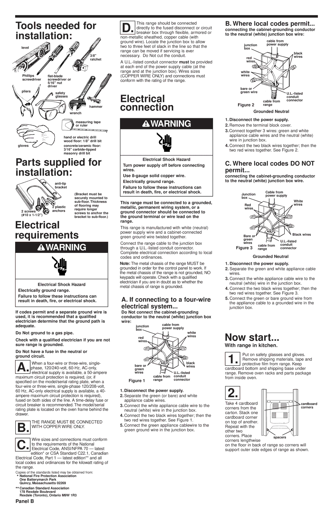
Tools needed for installation:
level
| 3/8" |
| ratchet |
Phillips | flat-blade |
screwdriver | screwdriver or |
| 5/16" nut |
| driver |
pliers | safety |
|
| glasses |
| hammer |
| wrench |
| measuring tape |
| or ruler |
| hand or electric drill |
| wood floor: 1/8" drill bit |
gloves | concrete/ceramic floor: |
| 3/16" carbide-tipped |
| masonry drill bit |
Parts supplied for installation:
anti-tip bracket
| | | (Bracket must be |
| | | securely mounted to |
| | | sub-floor. Thickness |
| | 2 plastic | of flooring may |
| | require longer |
| 2 screws | anchors |
| screws to anchor the |
| (#10 x 1-1/2") | |
| | bracket to sub-floor.) |
| | |
Electrical requirements
 WARNING
Electrical Shock Hazard
Electrically ground range.
Failure to follow these instructions can result in death, fire, or electrical shock.
If codes permit and a separate ground wire is used, it is recommended that a qualified electrician determine that the ground path is adequate.
Do Not ground to a gas pipe.
Check with a qualified electrician if you are not sure range is grounded.
Do Not have a fuse in the neutral or ground circuit.
When a four-wire or three-wire, single- A. phase, 120/240-volt, 60-Hz, AC-only,
electrical supply is available, a 50-ampere maximum circuit protection is required, (or, if specified on the model/serial rating plate, when a four-wire or three-wire, single-phase 120/208-volt, 60 Hz, AC-only electrical supply is available, a 40- ampere maximum circuit protection is required), fused on both sides of the line. A time-delay fuse or circuit breaker is recommended. The model/serial rating plate is located on the oven frame behind the drawer.
THE RANGE MUST BE CONNECTED B. WITH COPPER WIRE ONLY.
Wire sizes and connections must conform C. to the requirements of the National
Electrical Code, ANSI/NFPA 70 — latest edition* or CSA Standard C22.1, Canadian
Electrical Code, Part 1 — latest edition** and all local codes and ordinances for the kilowatt rating of the range.
Copies of the standards listed may be obtained from:
*National Fire Protection Association One Batterymarch Park
Quincy, Massachusetts 02269
**Canadian Standard Association 178 Rexdale Boulevard
Rexdale (Toronto), Ontario M9W 1R3
This range should be connected
D. directly to the fused disconnect or circuit breaker box through flexible, armored or
non-metallic sheathed, copper cable (with ground wire). Locate the junction box to allow two to three feet of slack in the line so that the range can be moved if servicing is ever necessary. Do Not cut the conduit.
A U.L.-listed conduit connector must be provided at each end of the power supply cable (at the range and at the junction box). Wires sizes (COPPER WIRE ONLY) and connections must conform with the rating of the range.
Electrical connection
 WARNING
Electrical Shock Hazard
Turn power supply off before connecting wires.
Use 8-gauge solid copper wire. Electrically ground range.
Failure to follow these instructions can result in death, fire, or electrical shock.
This range must be connected to a grounded, metallic, permanent wiring system, or a ground connector should be connected to the ground terminal or wire lead on the range.
This range is manufactured with white (neutral) power supply wire and a cabinet-connected green ground wire twisted together.
Connect the range cable to the junction box through a U.L.-listed conduit connector. Complete electrical connection according to local codes and ordinances.
Note: The metal chassis of the range MUST be grounded in order for the control panel to work. If the metal chassis of the range is not grounded, NO keypads will operate. Check with a qualified electrician if you are in doubt as to whether the metal chassis of range is grounded.
A. If connecting to a four-wire
electrical system...
Do Not connect the cabinet-grounding conductor to the neutral (white) junction box wire:
junction | cable from | |
power supply | |
box | |
| white |
| |
red | | wires |
| |
wires | | |
bare or | | black |
| wires |
green | | |
wires | | U.L.-listed |
| cable from | conduit |
Figure 1 | range | connector |
1.Disconnect the power supply.
2.Separate the green (or bare) and white appliance cable wires.
3.Connect the white appliance cable wire to the neutral (white) wire in the junction box.
4.Connect the two black wires together; then the two red wires together. See Figure 1.
5.Connect the green appliance cablewire to the green ground wire in the junction box.
B. Where local codes permit...
connecting the cabinet-grounding conductor to the neutral (white) junction box wire:
| cable from | |
junction | power supply |
box | | |
| | black |
red | | wires |
wires | | |
white | | |
wires | | |
bare or | | |
green wire | | U.L.-listed |
| |
| | conduit |
Figure 2 | cable from | connector |
range | |
Grounded Neutral
1.Disconnect the power supply.
2.Remove the terminal block cover.
3.Connect together 3 wires: green and white appliance cable wires and the neutral (white) wire in junction box.
4.Connect the two black wires together; then the two red wires together. See Figure 2.
C. Where local codes DO NOT
permit...
connecting the cabinet-grounding conductor to the neutral (white) junction box wire.
Cable from
Junction power supply box
White
Redwires wires
| Bare or | | Black wires |
| green | | U.L.-listed |
| wires | |
| cable from | conduit |
| Figure 3 |
| range | connector |
Grounded Neutral
1.Disconnect the power supply.
2.Separate the green and white appliance cable wires.
3.Connect the white appliance cable wire to the neutral (white) wire in the junction box.
4.Connect the two black wires together; then the two red wires together. See Figure 3.
5.Connect the green or bare ground wire from the appliance cable to a grounded wire in the junction box.
Now start...
With range in kitchen.
Put on safety glasses and gloves.
1. Remove shipping materials, tape and protective film from range. Keep
cardboard bottom and shipping base under range. Remove oven racks and parts package from inside oven.
| 2. | |
| Take 4 cardboard | cardboard |
| corners from the | corners |
| carton. Stack one | |
| cardboard corner | |
| on top of another. | |
| Repeat with the | |
| other two | |
| corners. Place | spacers |
| corners lengthwise |
| |
on the floor in back of range so corners will support outer side edges of range as shown.