Syrex IS-XN specifications
The Klaxon Syrex IS-XN is a state-of-the-art industrial signaling device designed to meet the demands of challenging environments. Engineered for reliability and efficiency, the Syrex IS-XN combines cutting-edge technology with a robust design, making it ideal for industrial applications, including manufacturing, oil and gas, and chemical processing.One of the standout features of the Syrex IS-XN is its powerful audio output. Producing up to 120 dB(A) of sound, it effectively captures attention in loud industrial settings. This high decibel level ensures that alarms can be heard over machinery noise and other ambient sounds, providing an essential layer of safety in the workplace. The device offers a variety of sound options, allowing users to select distinct alarm signals tailored to specific scenarios, ensuring that alerts are immediately recognized by personnel.
In addition to its audio capabilities, the Syrex IS-XN is equipped with innovative visual signaling options, including a vibrant LED strobe light. This combination of auditory and visual alerts enhances overall safety and situational awareness. The strobe light is highly visible even in daylight conditions, making it an effective tool for signaling emergencies, equipment malfunctions, or other critical situations.
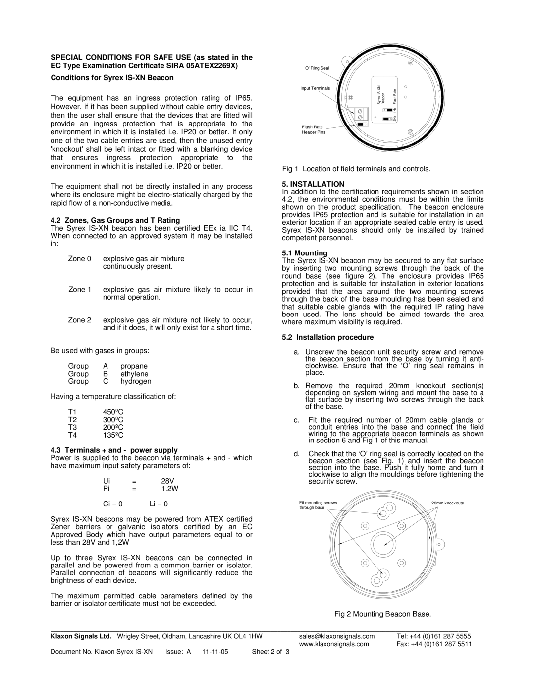
The Syrex IS-XN is designed for versatility, featuring multiple mounting options, including wall, pole, or ceiling installation. This adaptability allows it to be integrated seamlessly into various environments, regardless of space constraints. Its durable housing is constructed from high-quality materials that are resistant to harsh weather conditions, dust, and moisture, making it ideally suited for outdoor and industrial use.
Another significant advantage of the Syrex IS-XN is its ease of installation and maintenance. The device is designed with user-friendly features that facilitate quick setup and minimal downtime. Additionally, it is compatible with a range of power supplies, including AC and DC options, further enhancing its flexibility across different systems.
The Syrex IS-XN also prioritizes energy efficiency. Its innovative design minimizes power consumption without compromising performance, making it an environmentally friendly choice for businesses looking to reduce their carbon footprint.
Overall, the Klaxon Syrex IS-XN is a versatile, reliable, and effective industrial signaling solution. With its powerful audio alerts, vibrant visual signals, durable construction, and user-friendly features, it sets a new standard for alarm systems in demanding environments, ensuring safety and efficiency in critical operations.

