INSTALLATION
WIRING DIAGRAMS
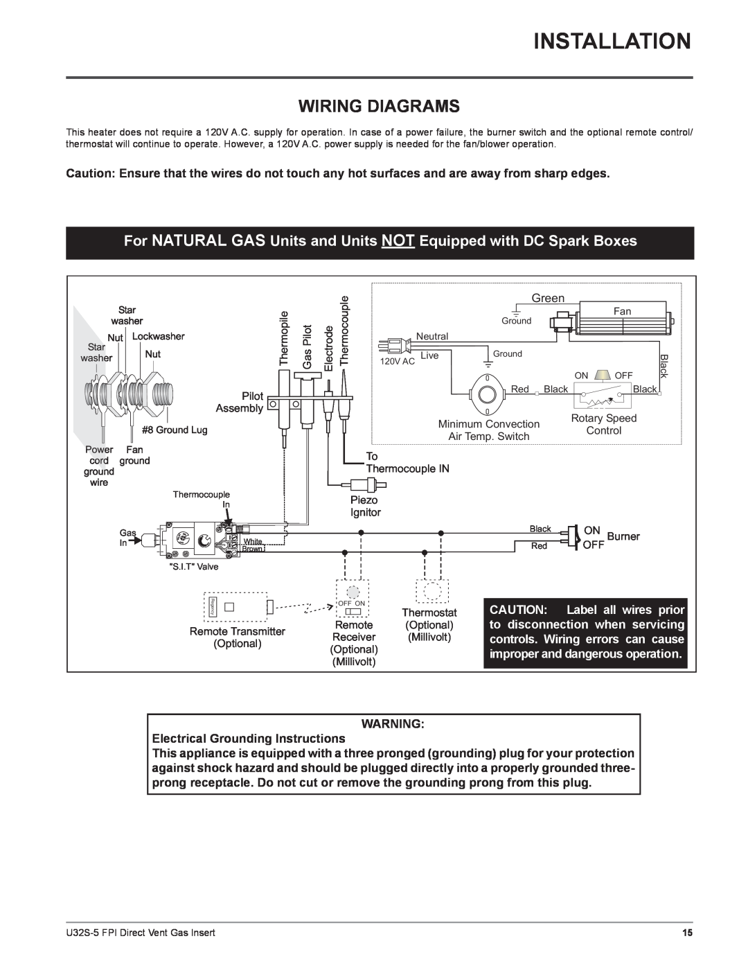
This heater does not require a 120V A.C. supply for operation. In case of a power failure, the burner switch and the optional remote control/ thermostat will continue to operate. However, a 120V A.C. power supply is needed for the fan/blower operation.
Caution: Ensure that the wires do not touch any hot surfaces and are away from sharp edges.
For NATURAL GAS Units and Units NOT Equipped with DC Spark Boxes
Gas In
Thermopile | GasPilot |
Pilot
Assembly ![]()
Thermocouple
In
ILO | T | O | N |
|
|
| |||
|
| I |
| |
P |
|
| H | White |
|
| FO | OL | |
|
| F |
|
|
|
|
|
| Brown |
"S.I.T" Valve
Regency
Remote Transmitter
(Optional)
Electrode Thermocouple |
| Green | ON | OFF | Black |
|
| ||||
|
|
|
| Fan |
|
|
| Ground |
|
|
|
| Neutral |
|
|
|
|
| 120V AC Live | Ground |
|
|
|
|
|
|
|
| |
|
| Red Black |
| Black |
|
| Minimum Convection | Rotary Speed |
| ||
| Control |
| |||
| Air Temp. Switch |
| |||
|
|
|
| ||
| To |
|
|
|
|
| Thermocouple IN |
|
|
|
|
Piezo
Ignitor
Black ![]() ON Burner
ON Burner
Red ![]() OFF
OFF
| OFF ON |
|
|
|
|
|
|
|
|
|
|
| CAUTION: Label all wires prior |
| |
Thermostat |
| ||||||
|
|
|
| ||||
Remote | (Optional) | to disconnection when servicing |
| ||||
Receiver | (Millivolt) | controls. Wiring errors can cause |
| ||||
(Optional) |
|
|
| improper and dangerous operation. |
| ||
(Millivolt) |
|
|
|
| |||
|
|
|
|
| |||
|
|
|
|
|
|
|
|
WARNING:
Electrical Grounding Instructions
This appliance is equipped with a three pronged (grounding) plug for your protection against shock hazard and should be plugged directly into a properly grounded three- prong receptacle. Do not cut or remove the grounding prong from this plug.
15 |