INSTALLATION
FACEPLATE AND DOOR FRAME INSTALLATION
| Kit# |
1 | Complete Faceplate with Switches |
1 | Door Frame |
1Bottom Louver
2Hinges
2 | Bottom Louver Brackets |
4 | Pan Head Screws |
1 | Wire Clip |
1Instruction Sheet
1)Bring the faceplate up in front of the unit and connect the red & black ON/OFF wires from the unit to the ON/OFF switch on the back of the left side of the faceplate.
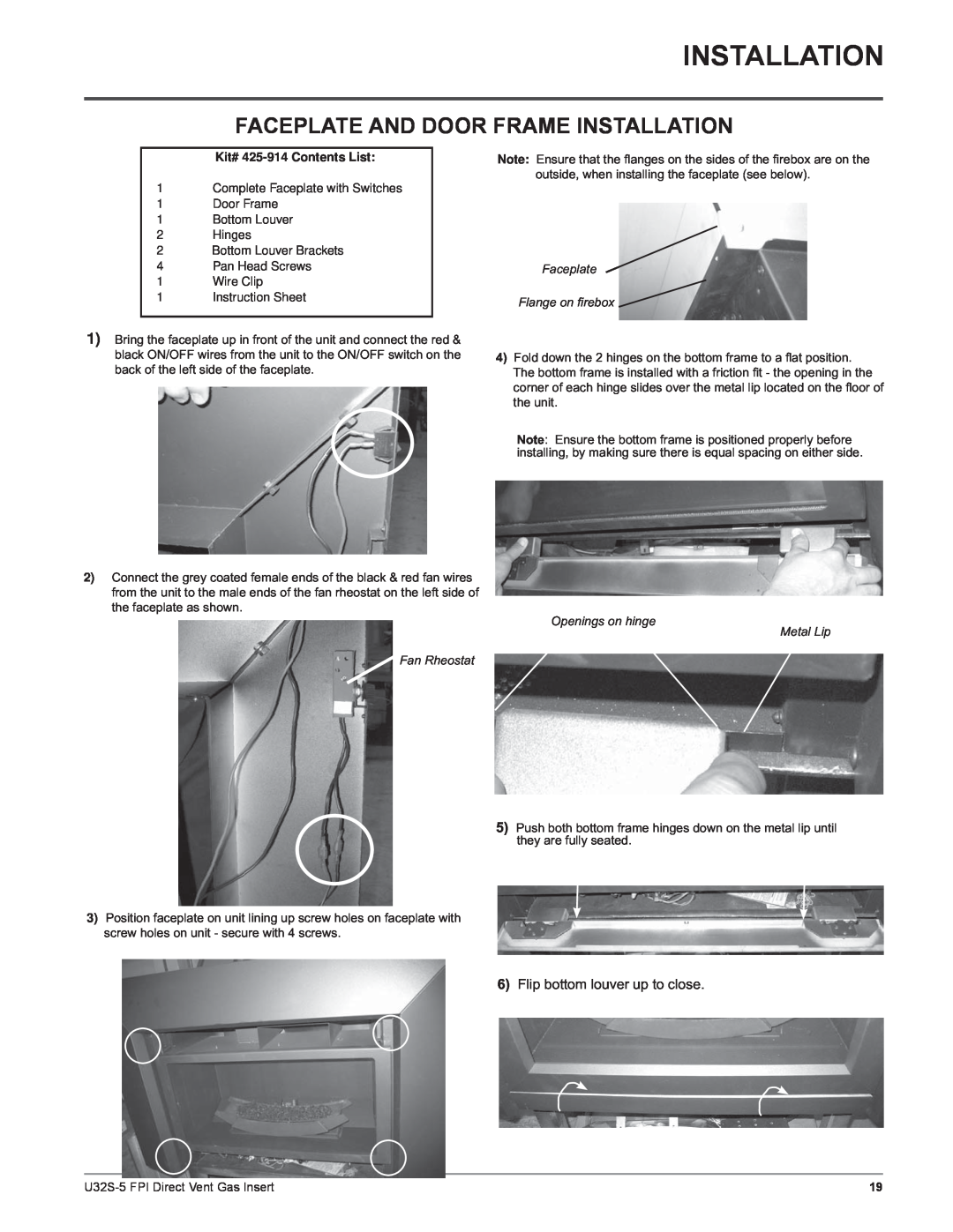
Note: Ensure that the flanges on the sides of the firebox are on the outside, when installing the faceplate (see below).
Faceplate
Flange on fi rebox ![]()
4)Fold down the 2 hinges on the bottom frame to a flat position. The bottom frame is installed with a friction fit - the opening in the corner of each hinge slides over the metal lip located on the floor of the unit.
2)Connect the grey coated female ends of the black & red fan wires from the unit to the male ends of the fan rheostat on the left side of the faceplate as shown.
Note: Ensure the bottom frame is positioned properly before installing, by making sure there is equal spacing on either side.
Openings on hinge
Metal Lip
Fan Rheostat
5) Push both bottom frame hinges down on the metal lip until they are fully seated.
3) Position faceplate on unit lining up screw holes on faceplate with screw holes on unit - secure with 4 screws.
6) Flip bottom louver up to close.
19 |