INSTALLATION
COMBUSTIBLE MANTEL | |||||||
| CLEARANCES |
| |||||
|
|
|
| G |
|
|
|
| 12 | 10 | 8 | 6 | 4 | 2 | 0 |
| 18 |
|
|
|
|
|
|
47” | 16 |
|
| 12" Mantel |
|
| |
|
|
|
|
|
| ||
(1194mm) | 14 |
|
|
|
|
| |
to ceiling |
|
|
|
| Mantel |
| |
| 12 |
|
|
|
|
|
|
| 10 |
|
|
|
|
|
|
|
| 17" |
|
|
|
|
|
| 8 |
|
|
|
|
|
|
| 6 |
|
|
| 13" |
| |
|
|
|
|
|
| ||
| 4 |
|
|
|
|
| Faceplate Top |
| 2 |
|
|
|
|
| |
|
|
|
|
|
|
| |
| 0 |
|
|
|
|
|
|
|
|
| 20“ |
| Top of |
|
|
|
| to floor |
|
|
| ||
|
|
| Unit |
|
| ||
|
|
|
|
|
|
| |
GAS CONNECTION
GAS CONNECTION WARNING: Only persons licensed to work with gas piping may make the necessary gas connections to this appliance.
1)If the appliance is to be installed into an existing chimney system, thoroughly clean the masonry or factory built fireplace.
2)The appliance is provided with an opening on the left hand side of the control compartment. A3/8" NPT gas supply pipe must be brought near this inlet hole.
3)Locate the center point where the vent will pass through the chimney above the appliance. Move the appliance into the exact location where it is to be installed. Ensure that the Insert is level.
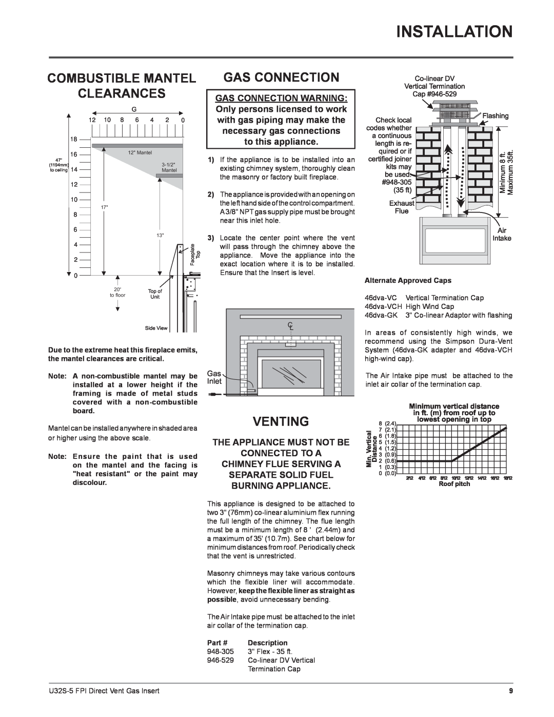
Alternate Approved Caps
Vertical Termination Cap | |
3" | |
Side View
Due to the extreme heat this fireplace emits, the mantel clearances are critical.
Note: A
Mantel can be installed anywhere in shaded area or higher using the above scale.
Note: Ensure the paint that is used on the mantel and the facing is "heat resistant" or the paint may discolour.
C
L
Gas
Inlet
VENTING
THE APPLIANCE MUST NOT BE
CONNECTED TO A
CHIMNEY FLUE SERVING A
SEPARATE SOLID FUEL
BURNING APPLIANCE.
This appliance is designed to be attached to two 3" (76mm)
Masonry chimneys may take various contours which the flexible liner will accommodate. However, keep the flexible liner as straight as possible, avoid unnecessary bending.
The Air Intake pipe must be attached to the inlet air collar of the termination cap.
Part # | Description |
3" Flex - 35 ft. | |
| Termination Cap |
In areas of consistently high winds, we recommend using the Simpson
The Air Intake pipe must be attached to the inlet air collar of the termination cap.
9 |