Manuals
/
Regency
/
Household Appliance
/
Indoor Fireplace
Regency
U32S-NG5 Flue Liner Installation, Gas Pipe Pressure Testing, Glass, Ceramic, Propane
Models:
U32S-NG5
U32S-LP5
1
10
36
36
Download
36 pages
50.46 Kb
7
8
9
10
11
12
13
14
Specs
Install
Parts list
Wiring Diagrams
Ignitor Wire Piezo Ignitor
Warranty
Dimension
Maintenance
Fan access plate
Burner Assembly
Page 10
Image 10
Page 9
Page 11
Page 10
Image 10
Page 9
Page 11
Contents
Owners
Installation Manual
U32 Sunrise Gas Insert
918-788
TO THE NEW OWNER
MAINTENANCE
TABLE OF CONTENTS
SAFETY LABEL
PARTS LIST
SAFETY LABEL
for the State of Massachusetts only
REQUIREMENTS
MA Code - CO Detector
5.08 Modifications to NFPA-54,Chapter
UNIT DIMENSIONS
U32S-5FPI Direct Vent Gas Insert
SPECIFICATIONS
INSTALLATION
FOR YOUR SAFETY
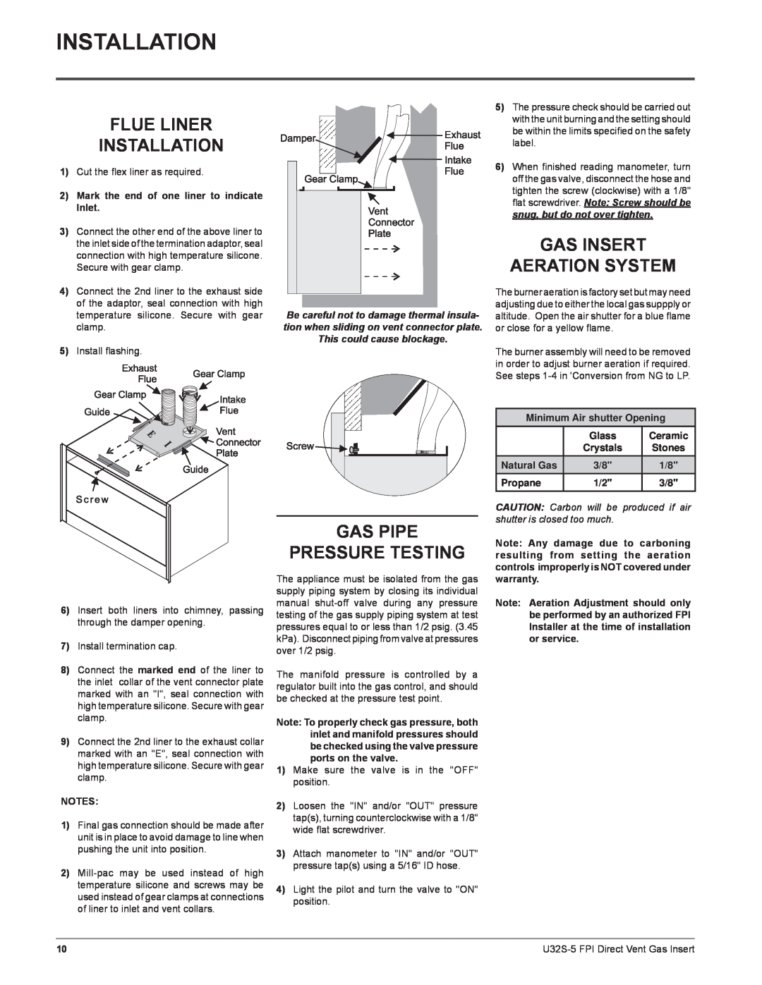
GAS PRESSURE TESTING
MINIMUM FIREPLACE DIMENSIONS
INSTALLATION
INSTALLATION CHECKLIST
MANUFACTURED MOBILE HOME ADDITIONAL REQUIREMENTS
VENTING
INSTALLATION
GAS CONNECTION
COMBUSTIBLE MANTEL
GAS PIPE PRESSURE TESTING
INSTALLATION
FLUE LINER INSTALLATION
GAS INSERT AERATION SYSTEM
CONVERSION KIT # 434-969FROM NG TO LP
INSTALLATION
U32S-5using SIT 820 NOVA Gas Valve
IF IN DOUBT DO NOT DO THIS CONVERSION
Do not overtighten the screw. Recommended to grip
INSTALLATION
Installer Notice
the wrench by the short side
Ignitor Wire Piezo Ignitor
INSTALLATION
Installation of the DC Sparker
Ground wire from kit
to the 120V wires Thermostat Wire Table
INSTALLATION
OPTIONAL REMOTE CONTROL
remote control the 120V wires
CAUTION Label all wires prior
INSTALLATION
WIRING DIAGRAMS
to disconnection when servicing
INSTALLATION
GLASS CRYSTAL OR OPTIONAL CERAMIC STONES
INSTALLATION
INSTALLATION ON BURNER
Minimum Air shutter Opening
Diagram Diagram 1a Diagram 1b Diagram
INSTALLATION
STANDARD FLUSH DOOR
Kit# 425-914Contents List
INSTALLATION
FACEPLATE AND DOOR FRAME INSTALLATION
Door Frame
8Lower the door frame gently into place
INSTALLATION
Completed Faceplate & Door Frame Installation
10Slide unit into final position
2 Hearth Trim Installation
INSTALLATION
OPTIONAL HEARTH TRIM INSTALLATION
4 Hearth Trim Installation
SHUTDOWN PROCEDURE
OPERATING INSTRUCTIONS
LIGHTING PROCEDURE
OPERATING INSTRUCTIONS
COPY OF LIGHTING INSTRUCTION PLATE
MAINTENANCE INSTRUCTIONS
OPERATING INSTRUCTIONS
DO NOT REMOVE THIS INSTRUCTION PLATE
DOOR GLASS
MAINTENANCE
GENERAL VENT MAINTENANCE
GLASS GASKET
FAN REMOVAL
MAINTENANCE
FAN MAINTENANCE
Burner
Pilot assembly wires
MAINTENANCE
Fan access plate
Base Cover
MAINTENANCE
REPLACING THE FAN
ON/OFF Wires
MAINTENANCE
VALVE ASSEMBLY REPLACEMENT
Burner
12 Disconnect the inlet gas line
MAINTENANCE
11Slightly lift out valve tray
U32S-5FPI Direct Vent Gas Insert
MAIN ASSEMBLY
PARTS LIST
Description
Description
PARTS LIST
BURNER ASSEMBLY
4 10 11 9 13
FACEPLATE AND DOORFRAME
PARTS LIST
1425-512Door Bottom Assembly 2425-513Frame Inside
3425-514Faceplate Outside 4425-942Hearth Trim
U32S-5FPI Direct Vent Gas Insert
U32S-5FPI Direct Vent Gas Insert
Conditions
WARRANTY
The Warranty Limited Lifetime
Exclusions
See the inside back cover for details
Top
Page
Image
Contents