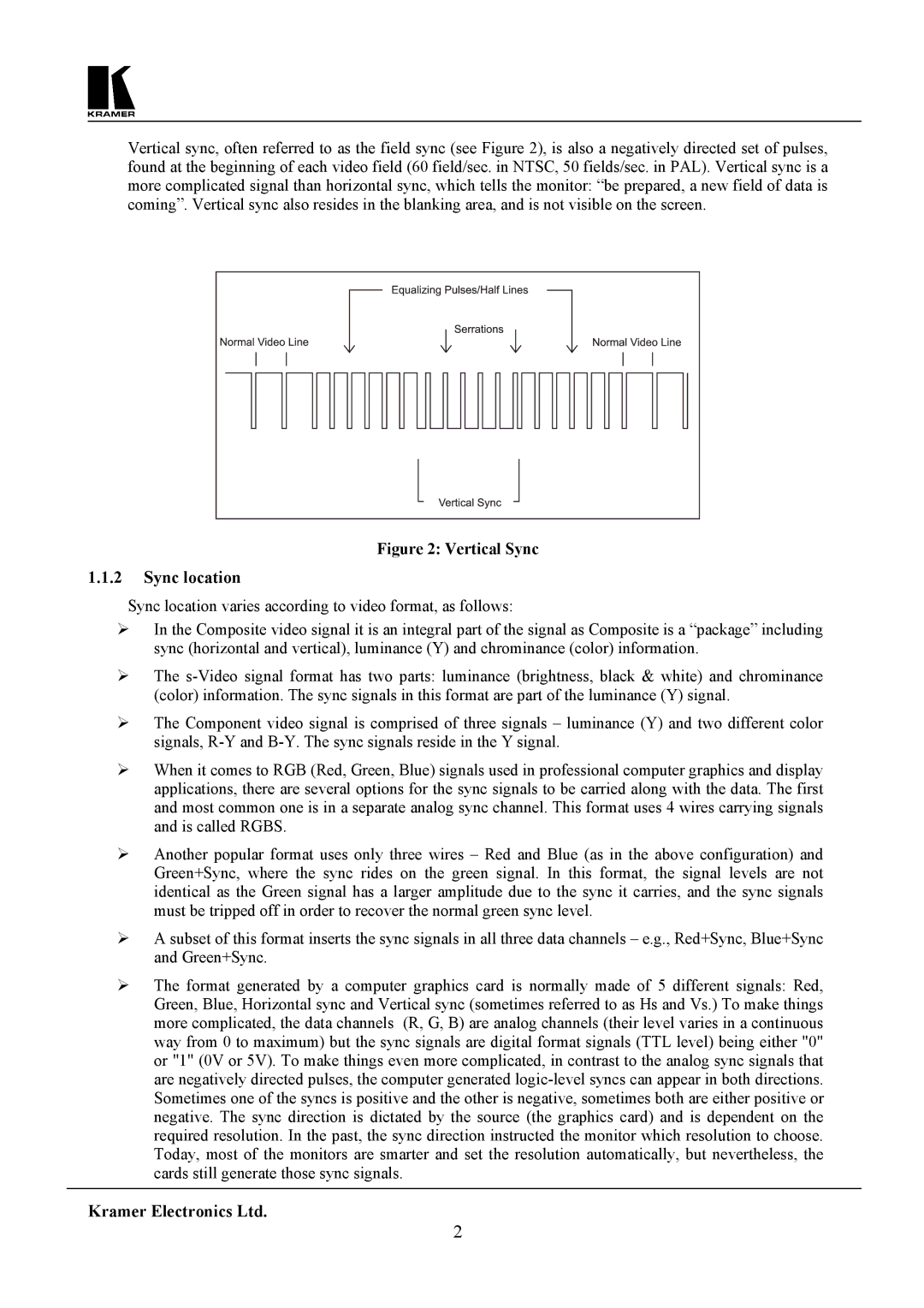
Vertical sync, often referred to as the field sync (see Figure 2), is also a negatively directed set of pulses, found at the beginning of each video field (60 field/sec. in NTSC, 50 fields/sec. in PAL). Vertical sync is a more complicated signal than horizontal sync, which tells the monitor: “be prepared, a new field of data is coming”. Vertical sync also resides in the blanking area, and is not visible on the screen.

Figure 2: Vertical Sync

1.1.2Sync location

Sync location varies according to video format, as follows:

In the Composite video signal it is an integral part of the signal as Composite is a “package” including sync (horizontal and vertical), luminance (Y) and chrominance (color) information.

The s-Video signal format has two parts: luminance (brightness, black & white) and chrominance (color) information. The sync signals in this format are part of the luminance (Y) signal.

The Component video signal is comprised of three signals – luminance (Y) and two different color signals, R-Y and B-Y. The sync signals reside in the Y signal.

When it comes to RGB (Red, Green, Blue) signals used in professional computer graphics and display applications, there are several options for the sync signals to be carried along with the data. The first and most common one is in a separate analog sync channel. This format uses 4 wires carrying signals and is called RGBS.

Another popular format uses only three wires – Red and Blue (as in the above configuration) and Green+Sync, where the sync rides on the green signal. In this format, the signal levels are not identical as the Green signal has a larger amplitude due to the sync it carries, and the sync signals must be tripped off in order to recover the normal green sync level.

A subset of this format inserts the sync signals in all three data channels – e.g., Red+Sync, Blue+Sync and Green+Sync.

The format generated by a computer graphics card is normally made of 5 different signals: Red, Green, Blue, Horizontal sync and Vertical sync (sometimes referred to as Hs and Vs.) To make things more complicated, the data channels (R, G, B) are analog channels (their level varies in a continuous way from 0 to maximum) but the sync signals are digital format signals (TTL level) being either "0" or "1" (0V or 5V). To make things even more complicated, in contrast to the analog sync signals that are negatively directed pulses, the computer generated logic-level syncs can appear in both directions. Sometimes one of the syncs is positive and the other is negative, sometimes both are either positive or negative. The sync direction is dictated by the source (the graphics card) and is dependent on the required resolution. In the past, the sync direction instructed the monitor which resolution to choose. Today, most of the monitors are smarter and set the resolution automatically, but nevertheless, the cards still generate those sync signals.

Kramer Electronics Ltd.

2

Page 4
Image 4
Kramer Electronics SG-6 user manual Sync location

SG-6 specifications

Kramer Electronics SG-6 is a versatile and compact signal generator designed for a wide range of applications in professional AV environments. Known for its robust build and reliable performance, the SG-6 is particularly favored in situations that require precise signal handling and testing, including video production, broadcasting, and AV installation.

One of the main features of the SG-6 is its ability to generate various signal types, including video, audio, and data formats. It supports multiple resolutions and refresh rates, ensuring compatibility with a diverse array of display technologies and standards. The device can output signals in formats such as composite video, component video, and even digital formats, making it a powerful tool for both legacy and modern AV systems.

In terms of technologies, the SG-6 utilizes advanced signal processing algorithms, which enhance the clarity and fidelity of the output signals. This ensures that users receive accurate and high-quality signals, which is crucial for testing and troubleshooting AV systems. The inclusion of sophisticated timing and synchronization capabilities allows the SG-6 to work seamlessly with various devices, ensuring that signal integrity remains intact throughout the transmission.

Another characteristic that sets the SG-6 apart is its user-friendly interface. The device features an intuitive control panel with clear indicators and buttons, allowing users to navigate through different settings and configurations with ease. Additionally, it supports remote management and configuration through integration with standard network protocols, further enhancing its usability in professional settings.

The compact design of the SG-6 is another advantage, making it easy to install in rack-mounted systems or portable setups. Its rugged construction ensures durability, so it can withstand the rigors of frequent use in dynamic environments.

Overall, the Kramer Electronics SG-6 is a powerful signal generator that combines versatility, reliability, and advanced technology, making it an essential tool for AV professionals who require precise signal generation and testing capabilities. Whether in a studio, live event, or installation environment, the SG-6 stands out as a go-to solution for effective signal management.