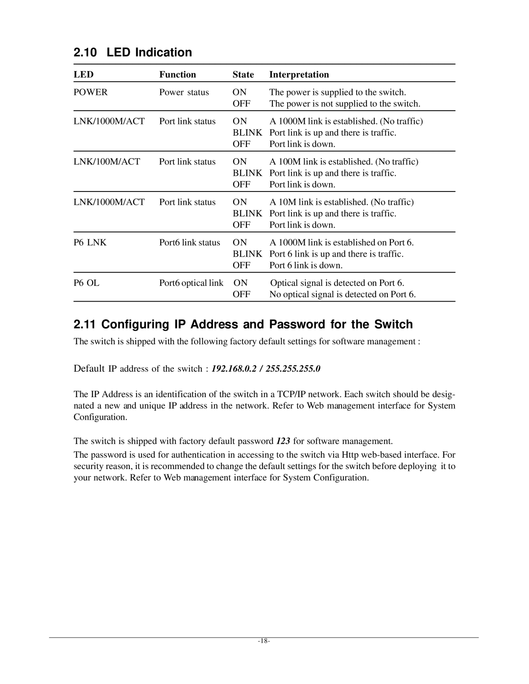
2.10 LED Indication
LED | Function | State | Interpretation |
POWER | Power status | ON | The power is supplied to the switch. |
|
| OFF | The power is not supplied to the switch. |
LNK/1000M/ACT | Port link status | ON | A 1000M link is established. (No traffic) |
|
| BLINK | Port link is up and there is traffic. |
|
| OFF | Port link is down. |
LNK/100M/ACT | Port link status | ON | A 100M link is established. (No traffic) |
|
| BLINK | Port link is up and there is traffic. |
|
| OFF | Port link is down. |
LNK/1000M/ACT | Port link status | ON | A 10M link is established. (No traffic) |
|
| BLINK | Port link is up and there is traffic. |
|
| OFF | Port link is down. |
P6 LNK | Port6 link status | ON | A 1000M link is established on Port 6. |
|
| BLINK | Port 6 link is up and there is traffic. |
|
| OFF | Port 6 link is down. |
P6 OL | Port6 optical link | ON | Optical signal is detected on Port 6. |
|
| OFF | No optical signal is detected on Port 6. |
2.11 Configuring IP Address and Password for the Switch
The switch is shipped with the following factory default settings for software management :
Default IP address of the switch : 192.168.0.2 / 255.255.255.0
The IP Address is an identification of the switch in a TCP/IP network. Each switch should be desig- nated a new and unique IP address in the network. Refer to Web management interface for System Configuration.
The switch is shipped with factory default password 123 for software management.
The password is used for authentication in accessing to the switch via Http
