SERVICING
Always disconnect the appliance from the electricity and gas mains before proceeding withanyservicingoperation.
12) REPLACING COMPONENTS
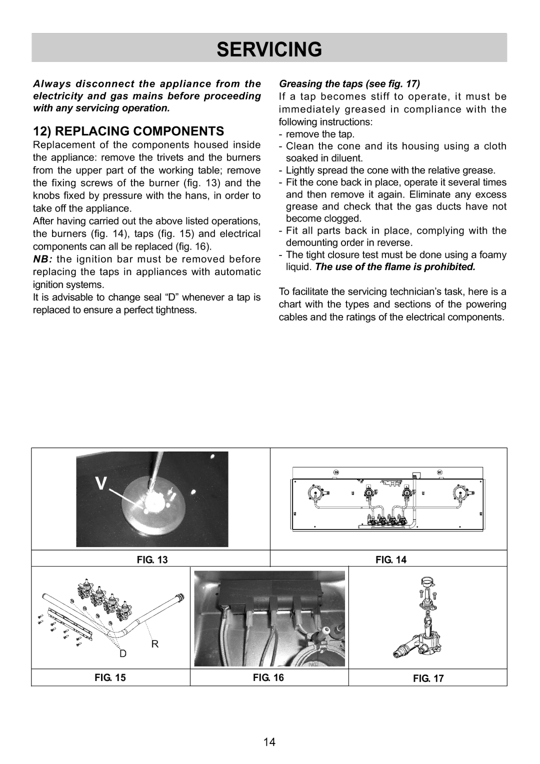
Replacement of the components housed inside the appliance: remove the trivets and the burners from the upper part of the working table; remove the fixing screws of the burner (fig. 13) and the knobs fixed by pressure with the hans, in order to take off the appliance.
After having carried out the above listed operations, the burners (fig. 14), taps (fig. 15) and electrical components can all be replaced (fig. 16).
NB: the ignition bar must be removed before replacing the taps in appliances with automatic ignitionsystems.
It is advisable to change seal “D” whenever a tap is replacedtoensureaperfecttightness.
Greasingthetaps(seefig.17)
If a tap becomes stiff to operate, it must be immediately greased in compliance with the following instructions:
- remove the tap.
- Clean the cone and its housing using a cloth soaked in diluent.
- Lightly spread the cone with the relative grease. - Fit the cone back in place, operate it several times and then remove it again. Eliminate any excess grease and check that the gas ducts have not become clogged.
- Fit all parts back in place, complying with the demounting order in reverse.
- The tight closure test must be done using a foamy
liquid. Theuseoftheflameisprohibited.
To facilitate the servicing technician’s task, here is a chart with the types and sections of the powering cables and the ratings of the electrical components.
FIG.13
FIG.14
FIG.15
FIG.16
FIG.17
14