
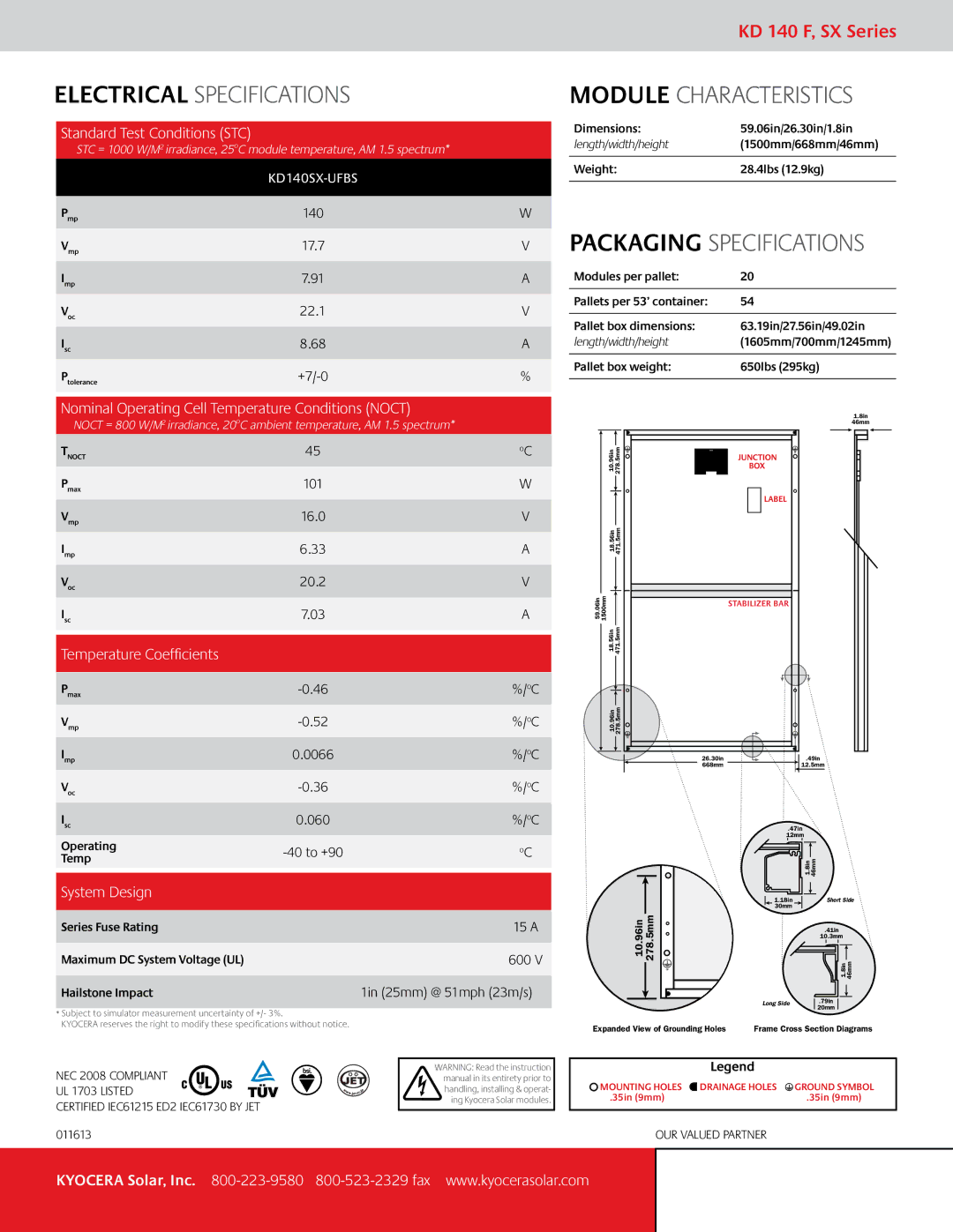
KD 140 F, SX series specifications
The Kyocera SX Series is a notable range of multifunctional printers designed for businesses that require efficient and reliable document handling. Among this impressive lineup, the Kyocera KD 140 F stands out due to its blend of advanced technology, user-friendly features, and compact design, making it an ideal choice for small to medium-sized offices.One of the main features of the Kyocera KD 140 F is its exceptional print quality. With a resolution of up to 1200 x 1200 dpi, it delivers sharp and clear text as well as vibrant images, ensuring that all printed materials meet professional standards. The printing speed of up to 40 pages per minute significantly increases productivity. Coupled with automatic duplex printing, users can save both time and paper, aligning with sustainable business practices.
The KD 140 F boasts a robust set of connectivity options that cater to the diverse needs of modern offices. It supports USB 2.0 and Ethernet interfaces, allowing for seamless integration into existing networks. Additionally, the printer is compatible with mobile printing technologies such as Apple AirPrint and Google Cloud Print, enabling users to print documents directly from their smartphones and tablets.
Another noteworthy aspect of the Kyocera KD 140 F is its long-lasting consumables. The device is engineered with Kyocera’s innovative ECOSYS technology, which significantly reduces waste and lowers the overall cost of ownership. Users can benefit from high-capacity toner cartridges, which allow for longer intervals between replacements, thus minimizing downtime and maintenance efforts.
Furthermore, the KD 140 F emphasizes user convenience. Its intuitive control panel provides easy navigation through various settings, and the compact design ensures it fits well in any workspace without occupying too much room. The printer also has an optional document feeder for efficient scanning and copying, enhancing its multifunction capabilities.
Security is a crucial concern for many businesses, and the Kyocera KD 140 F addresses this with robust security features. It offers secure printing options and user authentication processes to protect sensitive documents, thus ensuring that confidential information remains safe from unauthorized access.
In summary, the Kyocera SX Series KD 140 F combines high-quality printing, advanced connectivity, long-lasting consumables, and security features, making it a standout choice for businesses seeking a reliable and efficient multifunction printer. Its innovative technologies and user-friendly design are tailored to meet the evolving needs of the modern workplace, making it a valuable asset in any office environment.