Table of Contents
Section 3: Adjustments
Land Pride
Center Deck Height Adjustments
!DANGER!
Before making adjustments or performing maintenance on your mower, disengage PTO, shut off tractor and wait for all moving parts to stop before dismounting tractor. Disconnect the PTO driveline.
!CAUTION!
Block the decks before making cuttin4g height adjustments.
These adjustments should be made with mower
IMPORTANT: Refer to
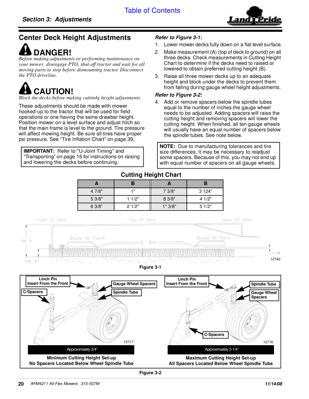
Refer to Figure 3-1:
1.Lower mower decks fully down on a flat level surface.
2.Make measurement (A) (top of deck to ground) on all three decks. Check measurements in Cutting Height Chart to determine if the decks need to raised or lowered to obtain preferred cutting height (B).
3.Raise all three mower decks up to an adequate height and block under the decks to prevent them from falling during gauge wheel height adjustments.
Refer to Figure 3-2:
4.Add or remove spacers below the spindle tubes equal to the number of inches the gauge wheel needs to be adjusted. Adding spacers will raise the cutting height and removing spacers will lower the cutting height. When finished, all ten gauge wheels will usually have an equal number of spacers below the spindle tubes. See note below.
NOTE: Due to manufacturing tolerances and tire size differences, it may be necessary to readjust some spacers. Because of this, you may not end up with equal number of spacers on all gauge wheels.
Cutting Height Chart
A |
| B |
| A | B |
4 7/8" |
| 1" |
| 7 3/8" | 3 124" |
5 3/8" | 1 | 1/2" |
| 8 3/8" | 4 1/2" |
6 3/8" | 2 | 1/2" |
| 1* 3/8" | 5 1/2" |
|
|
|
|
|
|
|
|
| 12742 |
| Figure |
|
|
Linch Pin |
| Linch Pin |
|
Insert From the Front | Gauge Wheel Spacers | Insert From the Front | Spindle Tube |
Spindle Tube |
| Gauge Wheel | |
|
|
| Spacers |
|
|
| |
| 12717 |
| 12716 |
Approximately 3/4” |
| Approximately 5 1/4” |
|
Minimum Cutting Height | Maximum Cutting Height | ||
No Spacers Located Below Wheel Spindle Tube | All Spacers Located Below Wheel Spindle Tube | ||
| Figure |
|
|
20 AFM4211 | 11/14/08 |