Land Pride | Table of Contents |
Section 1: Assembly and Set-Up
9.Attach the backhoe to the lower lift arms of the tractor using the pins that are attached to the pallet. Refer to Figure
10.Remove the two 7/8” bolts in order to free the top link. Refer to Figure
11.Mount the top link to the tractor. There is no correct side up for the top link. There are four different offset positions for the top link’s vertical and horizontal adjustment to match backhoe frame depending on your tractor’s
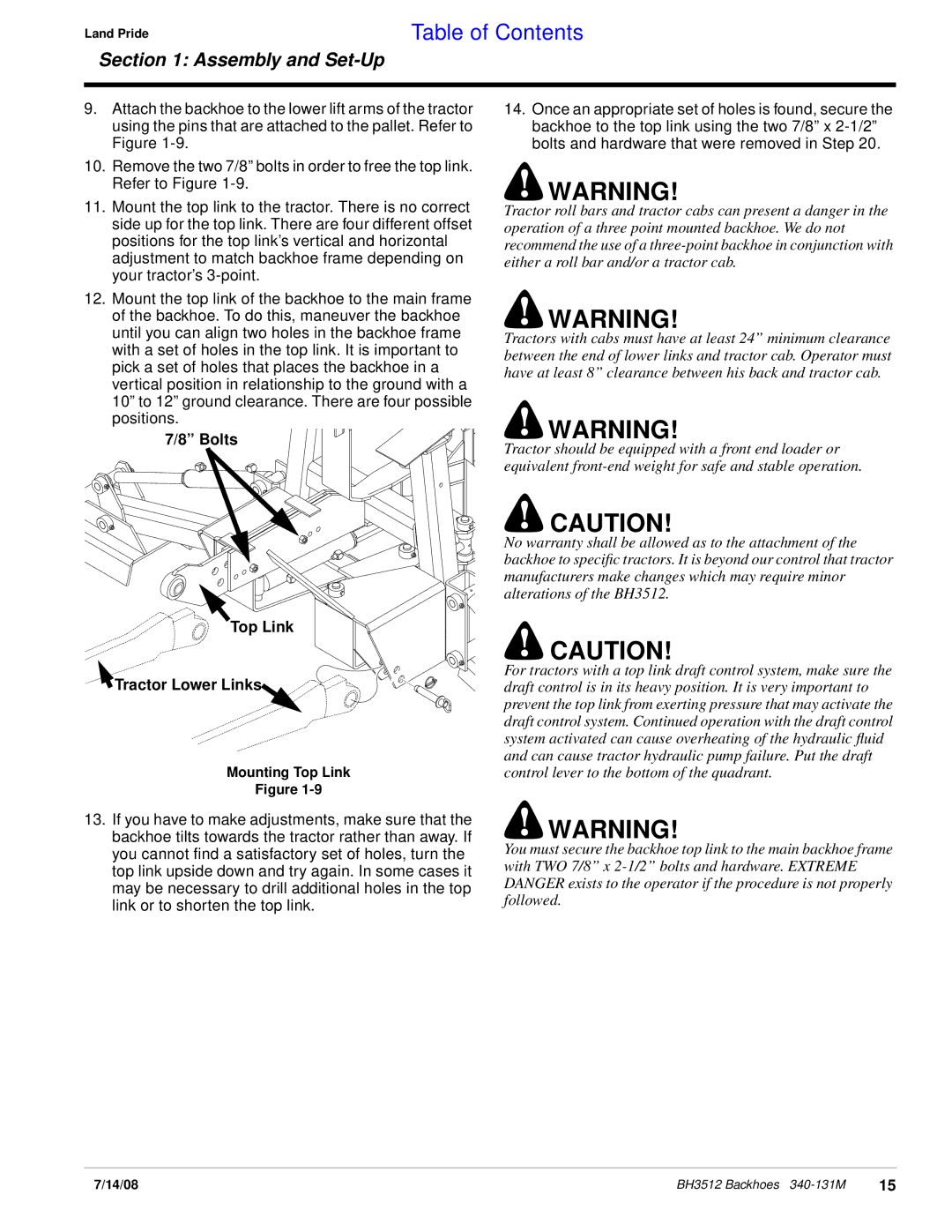
12.Mount the top link of the backhoe to the main frame of the backhoe. To do this, maneuver the backhoe until you can align two holes in the backhoe frame with a set of holes in the top link. It is important to pick a set of holes that places the backhoe in a vertical position in relationship to the ground with a 10” to 12” ground clearance. There are four possible positions.
7/8” Bolts
Top Link
 Tractor Lower Links
Mounting Top Link
Figure
13.If you have to make adjustments, make sure that the backhoe tilts towards the tractor rather than away. If you cannot find a satisfactory set of holes, turn the top link upside down and try again. In some cases it may be necessary to drill additional holes in the top link or to shorten the top link.
14.Once an appropriate set of holes is found, secure the backhoe to the top link using the two 7/8” x
!WARNING!
Tractor roll bars and tractor cabs can present a danger in the operation of a three point mounted backhoe. We do not recommend the use of a
!WARNING!
Tractors with cabs must have at least 24” minimum clearance between the end of lower links and tractor cab. Operator must have at least 8” clearance between his back and tractor cab.
!WARNING!
Tractor should be equipped with a front end loader or equivalent
!CAUTION!
No warranty shall be allowed as to the attachment of the backhoe to specific tractors. It is beyond our control that tractor manufacturers make changes which may require minor alterations of the BH3512.
!CAUTION!
For tractors with a top link draft control system, make sure the draft control is in its heavy position. It is very important to prevent the top link from exerting pressure that may activate the draft control system. Continued operation with the draft control system activated can cause overheating of the hydraulic fluid and can cause tractor hydraulic pump failure. Put the draft control lever to the bottom of the quadrant.
!WARNING!
You must secure the backhoe top link to the main backhoe frame with TWO 7/8” x
7/14/08 | BH3512 Backhoes | 15 |