Table of Contents
Section 1: Assembly and Set-Up
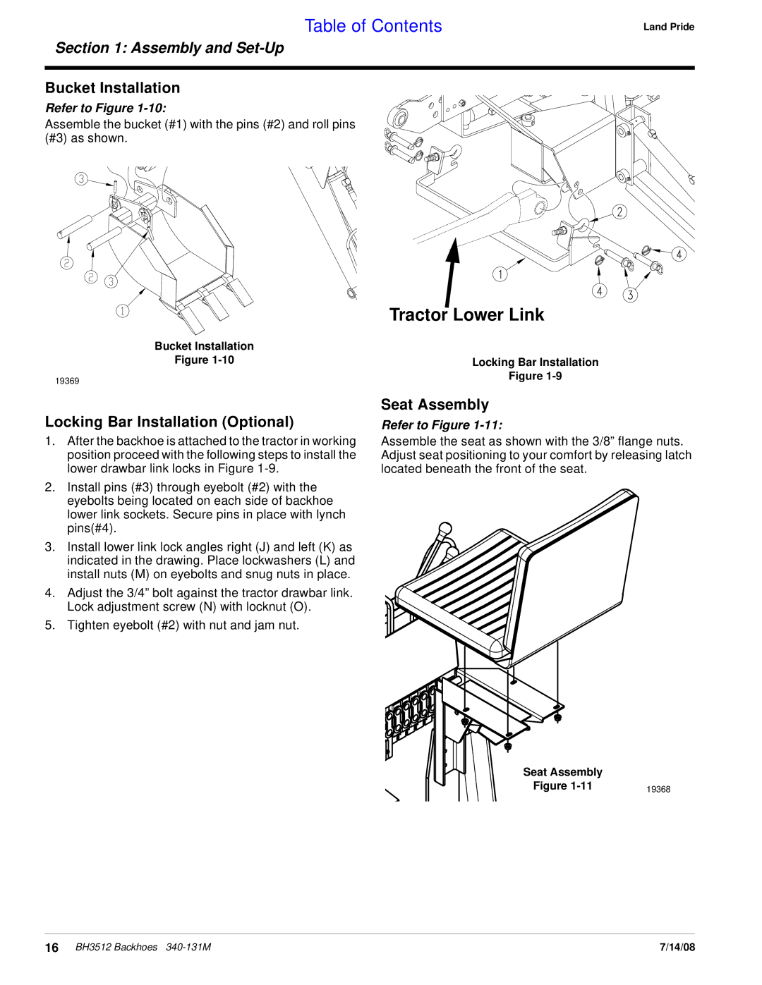
Bucket Installation
Refer to Figure 1-10:
Assemble the bucket (#1) with the pins (#2) and roll pins (#3) as shown.
Land Pride
| Tractor Lower Link |
Bucket Installation |
|
Figure | Locking Bar Installation |
19369 | Figure |
|
Locking Bar Installation (Optional)
1.After the backhoe is attached to the tractor in working position proceed with the following steps to install the lower drawbar link locks in Figure
2.Install pins (#3) through eyebolt (#2) with the eyebolts being located on each side of backhoe lower link sockets. Secure pins in place with lynch pins(#4).
3.Install lower link lock angles right (J) and left (K) as indicated in the drawing. Place lockwashers (L) and install nuts (M) on eyebolts and snug nuts in place.
4.Adjust the 3/4” bolt against the tractor drawbar link. Lock adjustment screw (N) with locknut (O).
5.Tighten eyebolt (#2) with nut and jam nut.
Seat Assembly
Refer to Figure 1-11:
Assemble the seat as shown with the 3/8” flange nuts. Adjust seat positioning to your comfort by releasing latch located beneath the front of the seat.
Seat Assembly |
|
Figure | 19368 |
16 BH3512 Backhoes | 7/14/08 |
