RC35120 RCM35120 specifications
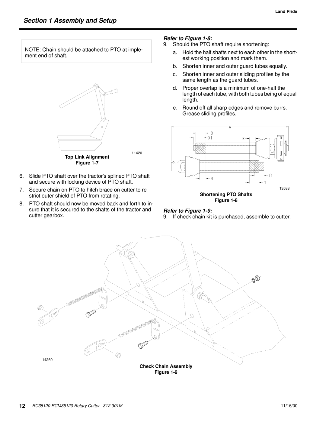
The Land Pride RC35120, part of the RCM35120 series, stands out in the agriculture and landscaping sectors for its robust design and exceptional performance. This remote-controlled mower is engineered to handle a variety of mowing tasks with precision and ease, making it a popular choice among professionals and hobbyists alike.One of its main features is the powerful engine that drives the RC35120, providing ample horsepower to tackle tough terrain and thick grass. The mower's high-performance engine ensures that it can operate efficiently even in challenging conditions, making it a reliable option for extensive landscaping projects.
The RC35120 is equipped with an advanced remote control system that allows operators to maneuver the mower from a safe distance. This feature is especially beneficial in hazardous or difficult-to-reach areas, as it reduces the risk of injury and increases operational efficiency. The ergonomic remote control design is intuitive, allowing users to adjust speed and direction with ease, enabling precise navigation around obstacles.
Another key characteristic of the RC35120 is its high-quality cutting deck. The mower features a reinforced deck that provides durability and longevity, capable of withstanding the rigors of regular use. The cutting height can be easily adjusted, allowing for flexibility in mowing preferences and different grass types. With a cutting width of 35 inches, the RC35120 allows operators to cover large areas swiftly, ultimately saving time and reducing labor costs.
Additionally, the RC35120 incorporates safety features that enhance both usage and operational peace of mind. The mower is built with protective guards to shield the operator from debris while mowing. Furthermore, automatic shut-off systems are implemented to halt operation in the event of a malfunction, promoting safety during use.
In terms of technology, the RC35120 integrates modern features such as easy maintenance access and an effective cooling system that ensures the engine stays within optimal temperature ranges during operation. These attributes not only prolong the life of the mower but also improve overall performance.
In summary, the Land Pride RC35120 RCM35120 mower is an exceptional tool that combines power, efficiency, and safety. Its innovative design, robust features, and advanced technologies make it an ideal choice for anyone looking to enhance their landscaping capabilities with a top-tier remote-controlled mower. Whether for commercial use or personal landscaping, this model delivers reliability and exceptional results.

