Langley/Empire DV-55SPP installation instructions Clearances, Checking Manifold Pressure

Models: DV-55SPP

1 20
Download 20 pages 33.65 Kb
Page 8
Image 8
Checking Manifold Pressure

Checking Manifold Pressure

Both Propane and Natural gas valves have a
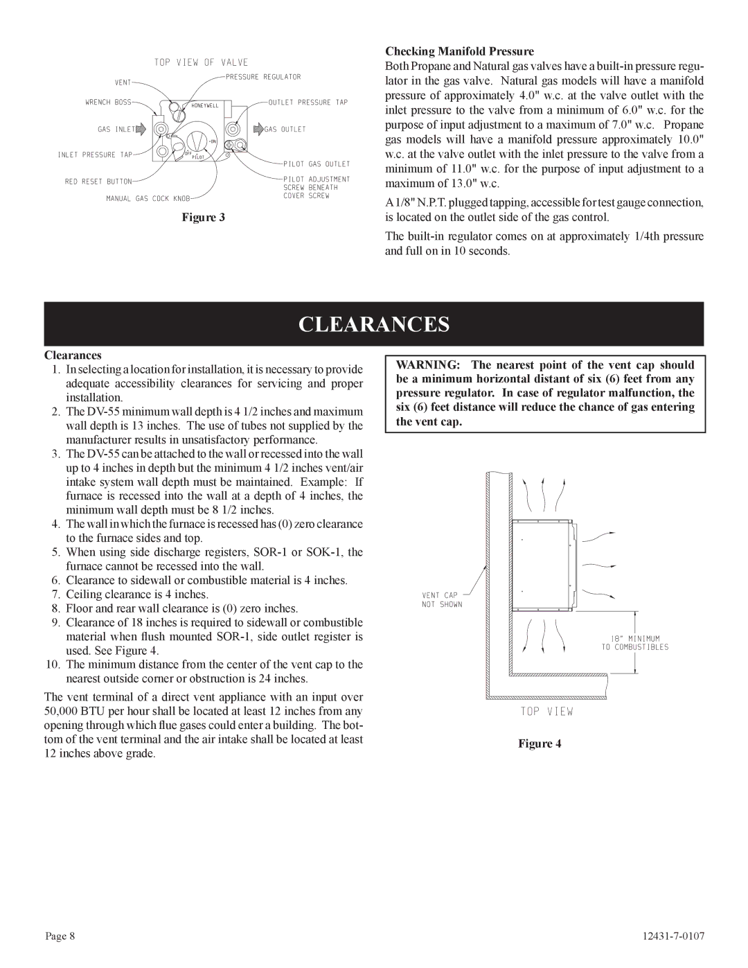
 built-in pressure regu- lator in the gas valve. Natural gas models will have a manifold pressure of approximately 4.0" w.c. at the valve outlet with the inlet pressure to the valve from a minimum of 6.0" w.c. for the purpose of input adjustment to a maximum of 7.0" w.c. Propane gas models will have a manifold pressure approximately 10.0" w.c. at the valve outlet with the inlet pressure to the valve from a minimum of 11.0" w.c. for the purpose of input adjustment to a maximum of 13.0" w.c.

Figure 3

A1/8" N.P.T. plugged tapping, accessible for test gauge connection,

is located on the outlet side of the gas control.

The built-in regulator comes on at approximately 1/4th pressure and full on in 10 seconds.

CLEARANCES

Clearances

1.In selecting a location for installation, it is necessary to provide adequate accessibility clearances for servicing and proper installation.

2.The DV-55 minimum wall depth is 4 1/2 inches and maximum wall depth is 13 inches. The use of tubes not supplied by the manufacturer results in unsatisfactory performance.

3.The DV-55 can be attached to the wall or recessed into the wall up to 4 inches in depth but the minimum 4 1/2 inches vent/air intake system wall depth must be maintained. Example: If furnace is recessed into the wall at a depth of 4 inches, the minimum wall depth must be 8 1/2 inches.

4.The wall in which the furnace is recessed has (0) zero clearance to the furnace sides and top.

5.When using side discharge registers, SOR-1 or SOK-1, the furnace cannot be recessed into the wall.

6.Clearance to sidewall or combustible material is 4 inches.

7.Ceiling clearance is 4 inches.

8.Floor and rear wall clearance is (0) zero inches.

9.Clearance of 18 inches is required to sidewall or combustible material when flush mounted SOR-1, side outlet register is used. See Figure 4.

10.The minimum distance from the center of the vent cap to the nearest outside corner or obstruction is 24 inches.

The vent terminal of a direct vent appliance with an input over 50,000 BTU per hour shall be located at least 12 inches from any opening through which flue gases could enter a building. The bot- tom of the vent terminal and the air intake shall be located at least 12 inches above grade.

WARNING: The nearest point of the vent cap should be a minimum horizontal distant of six (6) feet from any pressure regulator. In case of regulator malfunction, the six (6) feet distance will reduce the chance of gas entering the vent cap.

Figure 4

Page 8

12431-7-0107

Page 8
Image 8
Langley/Empire DV-55SPP Clearances, Checking Manifold Pressure, is located on the outlet side of the gas control