2 Demonstration Kit
Demo Board Block Diagram
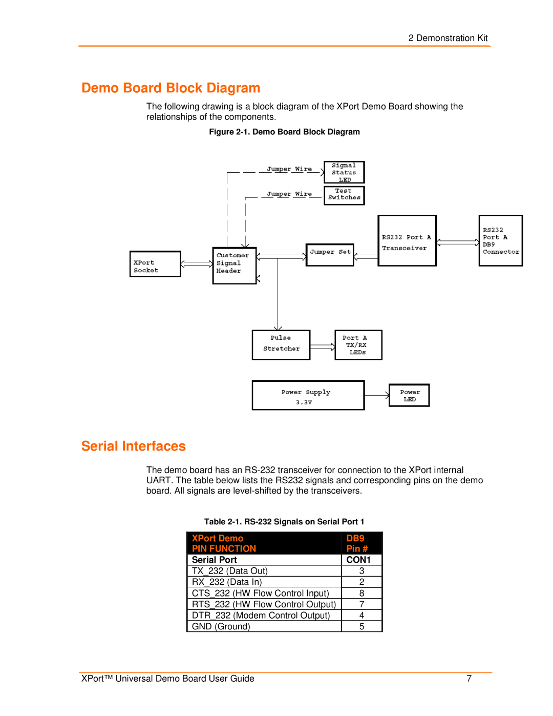
The following drawing is a block diagram of the XPort Demo Board showing the relationships of the components.
Figure 2-1. Demo Board Block Diagram
Serial Interfaces
The demo board has an
Table
| XPort Demo |
|
| DB9 |
| |
|
|
|
| |||
| PIN FUNCTION |
|
| Pin # |
| |
| Serial Port |
| CON1 | |||
| TX_232 (Data Out) | 3 |
| |||
| RX_232 (Data In) | 2 |
| |||
| CTS_232 | (HW Flow Control Input) | 8 |
| ||
| RTS_232 | (HW Flow Control Output) | 7 |
| ||
| DTR_232 (Modem Control Output) | 4 |
| |||
| GND (Ground) | 5 |
| |||
XPort™ Universal Demo Board User Guide | 7 |