2 Demonstration Kit
Power Supply
The demo board uses an external 3.3V regulated supply (included with kit).
General Control
The following tables denote the configuration of the demo board. Configuring the jumpers
Configuration Switch Bank
Table
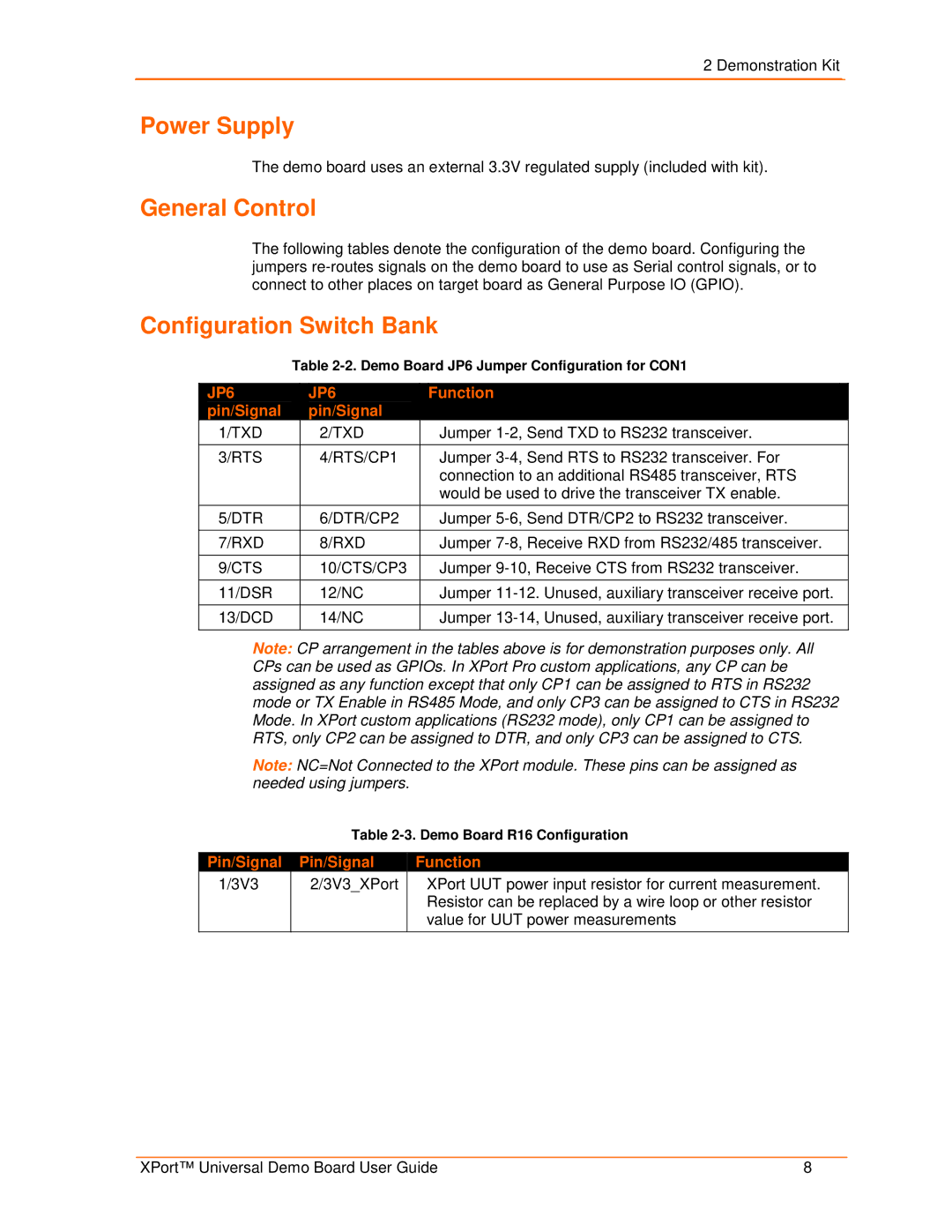
| JP6 |
|
| JP6 |
|
| Function |
|
|
|
|
|
|
| |||
| pin/Signal |
|
| pin/Signal |
|
|
|
|
| 1/TXD |
| 2/TXD |
| Jumper | |||
|
|
|
|
|
| |||
| 3/RTS |
| 4/RTS/CP1 |
| Jumper | |||
|
|
|
|
|
|
| connection to an additional RS485 transceiver, RTS | |
|
|
|
|
|
|
| would be used to drive the transceiver TX enable. | |
|
|
|
|
|
| |||
| 5/DTR |
| 6/DTR/CP2 |
| Jumper | |||
|
|
|
|
|
| |||
| 7/RXD |
| 8/RXD |
| Jumper | |||
|
|
|
|
|
| |||
| 9/CTS |
| 10/CTS/CP3 |
| Jumper | |||
|
|
|
|
|
| |||
| 11/DSR |
| 12/NC |
| Jumper | |||
|
|
|
|
|
| |||
| 13/DCD |
| 14/NC |
| Jumper | |||
|
|
|
|
|
|
|
|
|
Note: CP arrangement in the tables above is for demonstration purposes only. All CPs can be used as GPIOs. In XPort Pro custom applications, any CP can be assigned as any function except that only CP1 can be assigned to RTS in RS232 mode or TX Enable in RS485 Mode, and only CP3 can be assigned to CTS in RS232 Mode. In XPort custom applications (RS232 mode), only CP1 can be assigned to RTS, only CP2 can be assigned to DTR, and only CP3 can be assigned to CTS.
Note: NC=Not Connected to the XPort module. These pins can be assigned as needed using jumpers.
Table
Pin/Signal | Pin/Signal | Function | |
1/3V3 | 2/3V3_XPort | XPort UUT power input resistor for current measurement. | |
|
| Resistor can be replaced by a wire loop or other resistor | |
|
| value for UUT power measurements | |
|
|
|
XPort™ Universal Demo Board User Guide | 8 |