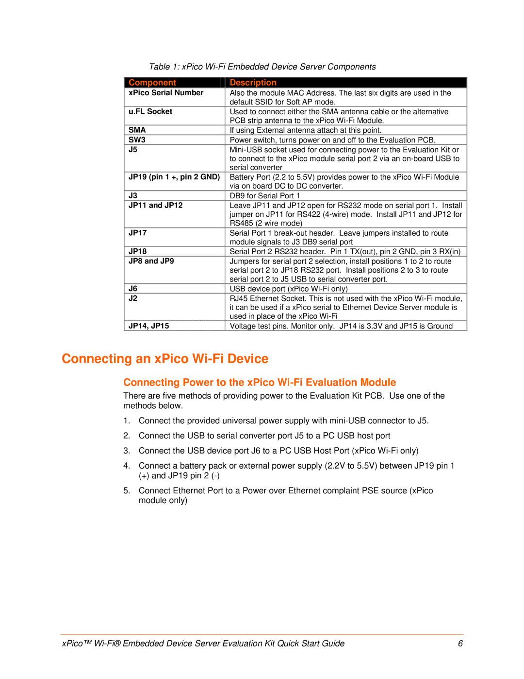
Table 1: xPico
Component | Description |
xPico Serial Number | Also the module MAC Address. The last six digits are used in the |
| default SSID for Soft AP mode. |
u.FL Socket | Used to connect either the SMA antenna cable or the alternative |
| PCB strip antenna to the xPico |
SMA | If using External antenna attach at this point. |
SW3 | Power switch, turns power on and off to the Evaluation PCB. |
J5 | |
| to connect to the xPico module serial port 2 via an |
| serial converter |
JP19 (pin 1 +, pin 2 GND) | Battery Port (2.2 to 5.5V) provides power to the xPico |
| via on board DC to DC converter. |
J3 | DB9 for Serial Port 1 |
JP11 and JP12 | Leave JP11 and JP12 open for RS232 mode on serial port 1. Install |
| jumper on JP11 for RS422 |
| RS485 (2 wire mode) |
JP17 | Serial Port 1 |
| module signals to J3 DB9 serial port |
JP18 | Serial Port 2 RS232 header. Pin 1 TX(out), pin 2 GND, pin 3 RX(in) |
JP8 and JP9 | Jumpers for serial port 2 selection, install positions 1 to 2 to route |
| serial port 2 to JP18 RS232 port. Install positions 2 to 3 to route |
| serial port 2 to J5 USB to serial converter port. |
J6 | USB device port (xPico |
J2 | RJ45 Ethernet Socket. This is not used with the xPico |
| it can be used if a xPico serial to Ethernet Device Server module is |
| used in place of the xPico |
JP14, JP15 | Voltage test pins. Monitor only. JP14 is 3.3V and JP15 is Ground |
Connecting an xPico Wi-Fi Device
Connecting Power to the xPico Wi-Fi Evaluation Module
There are five methods of providing power to the Evaluation Kit PCB. Use one of the methods below.
1.Connect the provided universal power supply with
2.Connect the USB to serial converter port J5 to a PC USB host port
3.Connect the USB device port J6 to a PC USB Host Port (xPico
4.Connect a battery pack or external power supply (2.2V to 5.5V) between JP19 pin 1
(+) and JP19 pin 2
5.Connect Ethernet Port to a Power over Ethernet complaint PSE source (xPico module only)
xPico™ | 6 |