M o u n t i n g a n d i n s t a l l a t i o n
Your new Opti Series crossover comes complete with all required mounting hardware. |
|
Please read the Installation Precautions section below before installing your Lanzar Opti signal processor, and then refer to the diagrams provided to connect power, |
|
audio input and output connections according to your own system configuration requirements. |
|
Precautions |
|
Mark the location for the mounting screw holes by positioning the crossover where you wish to install it and use a scribe (or one of the mounting screws) inserted |
|
in each of the mounting holes to mark the mounting surface. If the mounting surface is carpeted, measure the hole centers and mark with a felt tip pen. |
|
Before you drill or cut any holes, investigate your car’s layout very carefully. Take care when you work near the gas tank, fuel lines, hydraulic line and electrical wiring. |
|
Do not operate the signal processor when it is unmounted. Attach all audio system components securely within the automobile to prevent damage, especially in an |
|
accident. | 12 |
Do not mount this signal processor so that the wire connections are unprotected or in a pinched condition, or likely to be damaged by nearby objects. Be sure to |
select a location inside your vehicle which has adequate ventilation.
Before making or breaking power connections in your system, disconnect the vehicle battery. Confirm that your head unit or other equipment is turned off while connecting the input and output jacks.
If you need to replace the power fuse, only replace it with a fuse identical to that supplied with the system. Using a fuse of a different type or rating may result in damage to your system which isn’t covered by the manufacturer’s warranty.![]()
![]()
![]()
![]()
![]()
![]()
![]()
![]()
![]()
![]()
![]()
![]()
![]()
![]()
![]()
![]()
![]()
![]()
![]()
![]()
![]()
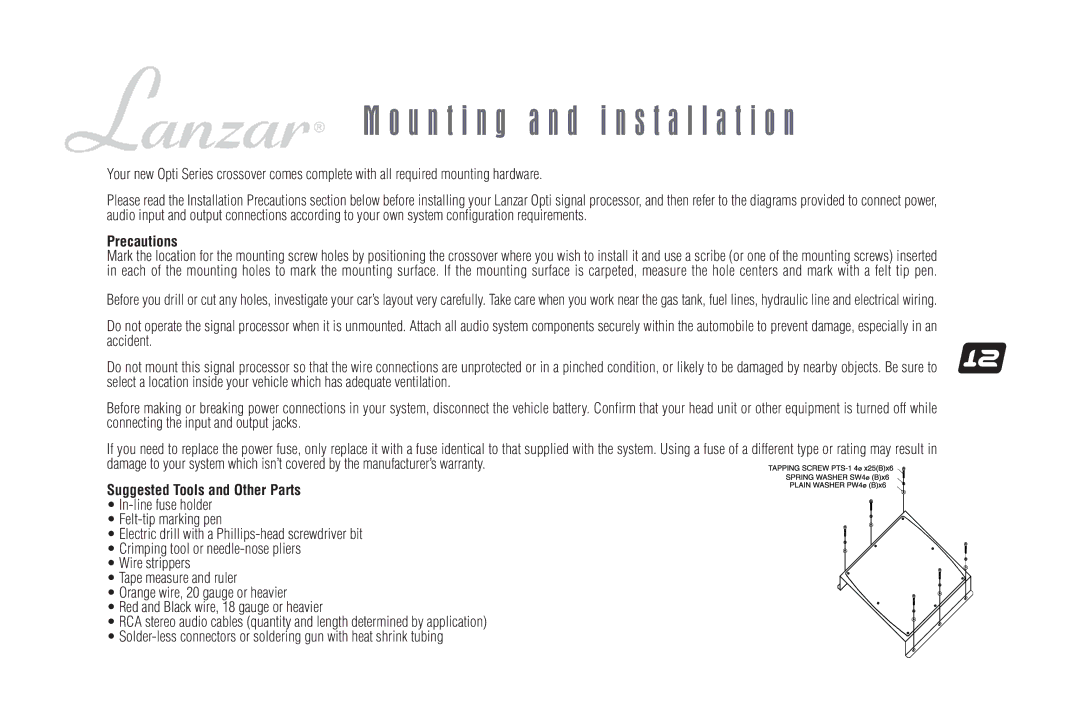
Suggested Tools and Other Parts
•
•
•Electric drill with a
• Crimping tool or
• Wire strippers
• Tape measure and ruler
• Orange wire, 20 gauge or heavier
•Red and Black wire, 18 gauge or heavier
•RCA stereo audio cables (quantity and length determined by application)
•