Offset Elbow Assembly
Offset elbows install the same as chimney sections. First, snap the inner section INTO the preceding inner section of flue. Check connec- tion by pulling up slightly to ensure a tight fit. Next, the outer sections snap lock OVER the preceding outer section of chimney. Again, check outer section by pulling up slightly to ensure proper connection is made.
Return Elbow Assembly
Return elbows install the same way as round terminations and stabilizers:
Step 1. Hold return elbow over top of last chimney section.
Step 2. Center inner slip section into inner flue
Step 3. Center
Step 4. Pull up slightly on return elbow to ensure locking joint has firmly engaged.
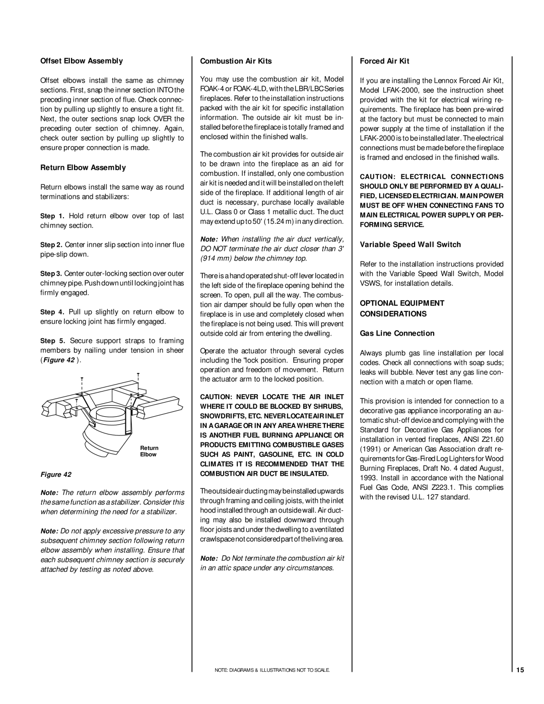
Step 5. Secure support straps to framing members by nailing under tension in sheer (Figure 42 ).
Return
Elbow
Figure 42
Note: The return elbow assembly performs the same function as a stabilizer. Consider this when determining the need for a stabilizer.
Note: Do not apply excessive pressure to any subsequent chimney section following return elbow assembly when installing. Ensure that each subsequent chimney section is securely attached by testing as noted above.
Combustion Air Kits
You may use the combustion air kit, Model
The combustion air kit provides for outside air to be drawn into the fireplace as an aid for combustion. If installed, only one combustion air kit is needed and it will be installed on the left side of the fireplace. If additional length of air duct is necessary, purchase locally available U.L. Class 0 or Class 1 metallic duct. The duct may extend up to 50' (15.24 m) in any direction.
Note: When installing the air duct vertically, DO NOT terminate the air duct closer than 3' (914 mm) below the chimney top.
There is a hand operated
Operate the actuator through several cycles including the "lock position. Ensuring proper operation and freedom of movement. Return the actuator arm to the locked position.
CAUTION: NEVER LOCATE THE AIR INLET WHERE IT COULD BE BLOCKED BY SHRUBS, SNOWDRIFTS, ETC. NEVER LOCATE AIR INLET IN A GARAGE OR IN ANY AREA WHERE THERE IS ANOTHER FUEL BURNING APPLIANCE OR PRODUCTS EMITTING COMBUSTIBLE GASES SUCH AS PAINT, GASOLINE, ETC. IN COLD CLIMATES IT IS RECOMMENDED THAT THE COMBUSTION AIR DUCT BE INSULATED.
The outside air ducting may be installed upwards through framing and ceiling joists, with the inlet hood installed through an outside wall. Air duct- ing may also be installed downward through floor joists and under the dwelling to a ventilated crawlspace not considered part of the living area.
Note: Do Not terminate the combustion air kit in an attic space under any circumstances.
NOTE: DIAGRAMS & ILLUSTRATIONS NOT TO SCALE.
Forced Air Kit
If you are installing the Lennox Forced Air Kit, Model
CAUTION: ELECTRICAL CONNECTIONS SHOULD ONLY BE PERFORMED BY A QUALI- FIED, LICENSED ELECTRICIAN. MAIN POWER MUST BE OFF WHEN CONNECTING FANS TO MAIN ELECTRICAL POWER SUPPLY OR PER- FORMING SERVICE.
Variable Speed Wall Switch
Refer to the installation instructions provided with the Variable Speed Wall Switch, Model VSWS, for installation details.
OPTIONAL EQUIPMENT
CONSIDERATIONS
Gas Line Connection
Always plumb gas line installation per local codes. Check all connections with soap suds; leaks will bubble. Never test any gas line con- nection with a match or open flame.
This provision is intended for connection to a decorative gas appliance incorporating an au- tomatic
15