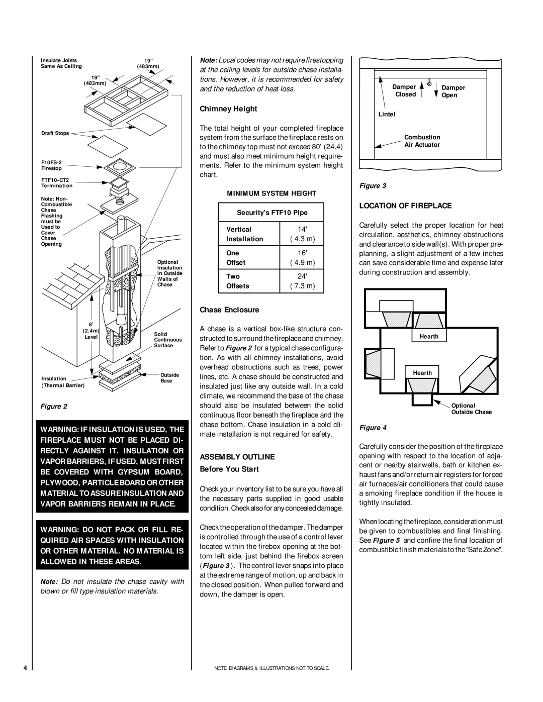
Insulate Joists
Same As Ceiling
19"
(483mm)
Draft Stops ![]()
Firestop ![]()
FTF10-CT2
Termination
Note: Non- Combustible Chase Flashing must be Used to Cover Chase Opening
8'
(2.4m)
Level
Insulation
(Thermal Barrier)
19"
(483mm)
Optional
Insulation
in Outside
Walls of
Chase
Solid
Continuous
Surface
![]() Outside Base
Outside Base
Note: Local codes may not require firestopping at the ceiling levels for outside chase installa- tions. However, it is recommended for safety and the reduction of heat loss.
Chimney Height
The total height of your completed fireplace system from the surface the fireplace rests on to the chimney top must not exceed 80' (24.4) and must also meet minimum height require- ments. Refer to the minimum system height chart.
MINIMUM SYSTEM HEIGHT
Security's FTF10 Pipe
Vertical | 14' |
Installation | ( 4.3 m) |
|
|
One | 16' |
Offset | ( 4.9 m) |
|
|
Two | 24' |
Offsets | ( 7.3 m) |
|
|
Chase Enclosure
A chase is a vertical
Damper | Damper |
Closed | Open |
Lintel |
|
Combustion |
|
Air Actuator |
|
Figure 3
LOCATION OF FIREPLACE
Carefully select the proper location for heat circulation, aesthetics, chimney obstructions and clearance to side wall(s). With proper pre- planning, a slight adjustment of a few inches can save considerable time and expense later during construction and assembly.
Hearth |
Hearth |
4
Figure 2
WARNING: IF INSULATION IS USED, THE FIREPLACE MUST NOT BE PLACED DI- RECTLY AGAINST IT. INSULATION OR VAPOR BARRIERS, IF USED, MUST FIRST BE COVERED WITH GYPSUM BOARD, PLYWOOD, PARTICLE BOARD OR OTHER MATERIAL TO ASSURE INSULATION AND VAPOR BARRIERS REMAIN IN PLACE.
WARNING: DO NOT PACK OR FILL RE- QUIRED AIR SPACES WITH INSULATION OR OTHER MATERIAL. NO MATERIAL IS ALLOWED IN THESE AREAS.
Note: Do not insulate the chase cavity with blown or fill type insulation materials.
should also be insulated between the solid continuous floor beneath the fireplace and the chase bottom. Chase insulation in a cold cli- mate installation is not required for safety.
ASSEMBLY OUTLINE
Before You Start
Check your inventory list to be sure you have all the necessary parts supplied in good usable condition. Check also for any concealed damage.
Check the operation of the damper. The damper is controlled through the use of a control lever located within the firebox opening at the bot- tom left side, just behind the firebox screen (Figure 3 ). The control lever snaps into place at the extreme range of motion, up and back in the closed position. When pulled forward and down, the damper is open.
NOTE: DIAGRAMS & ILLUSTRATIONS NOT TO SCALE.
Optional |
Outside Chase |
Figure 4
Carefully consider the position of the fireplace opening with respect to the location of adja- cent or nearby stairwells, bath or kitchen ex- haust fans and/or return air registers for forced air furnaces/air conditioners that could cause a smoking fireplace condition if the house is tightly insulated.
When locating the fireplace, consideration must be given to combustibles and final finishing. See Figure 5 and confine the final location of combustible finish materials to the "Safe Zone".