The pressure regulator on manual models is preset and locked to avoid tampering. If the pressure is not as specified in the Technical Details Chart on page 10, replace the regulator with P/N 110353 for natural gas and P/N 120341 for propane (L.P.G.) heaters.
Replace the test point plug after pressure measurement ensuring no gas leaks.
Step 4. Placing the Logs
WARNING: DO NOT ADD EXTRA LOGS OR ORNAMENTS SUCH AS PINE CONES, VER- MICULITE OR ROCK WOOL. USING THESE ADDED ITEMS CAN CAUSE SOOTING.
WARNING: DO NOT PLACE ANY LAVA ROCK ON LOGS OR BURNERS. THIS MAY CAUSE SOOTING. ONLY PLACE LAVA ROCK ON FLOOR OF FIREPLACE.
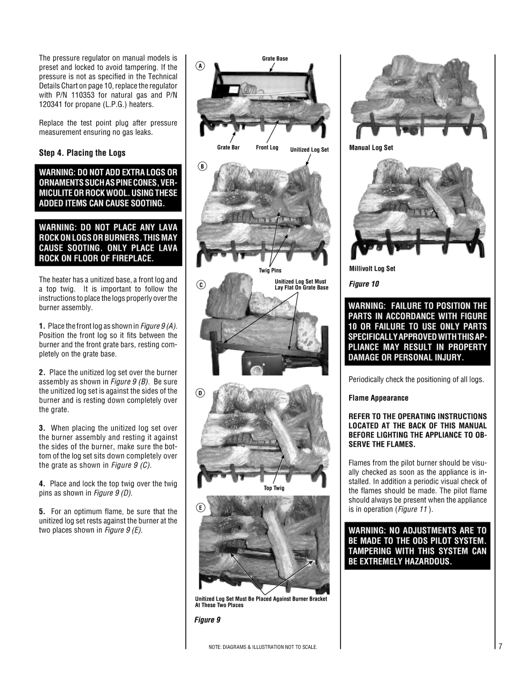
The heater has a unitized base, a front log and a top twig. It is important to follow the instructions to place the logs properly over the burner assembly.
1.Place the front log as shown in Figure 9 (A). Position the front log so it fits between the burner and the front grate bars, resting com- pletely on the grate base.
2.Place the unitized log set over the burner assembly as shown in Figure 9 (B). Be sure the unitized log set is against the sides of the burner and is resting down completely over the grate.
3.When placing the unitized log set over the burner assembly and resting it against the sides of the burner, make sure the bot- tom of the log set sits down completely over the grate as shown in Figure 9 (C).
4.Place and lock the top twig over the twig pins as shown in Figure 9 (D).
5.For an optimum flame, be sure that the unitized log set rests against the burner at the two places shown in Figure 9 (E).
Grate Base
A
Grate Bar | Front Log | Unitized Log Set |
|
|
B
| Twig Pins | |
C | Unitized Log Set Must | |
Lay Flat On Grate Base | ||
|
D
Top Twig
E
Unitized Log Set Must Be Placed Against Burner Bracket At These Two Places
Figure 9
NOTE: DIAGRAMS & ILLUSTRATION NOT TO SCALE.
Manual Log Set
Millivolt Log Set
Figure 10
WARNING: FAILURE TO POSITION THE PARTS IN ACCORDANCE WITH FIGURE 10 OR FAILURE TO USE ONLY PARTS SPECIFICALLY APPROVED WITH THIS AP- PLIANCE MAY RESULT IN PROPERTY DAMAGE OR PERSONAL INJURY.
Periodically check the positioning of all logs.
Flame Appearance
REFER TO THE OPERATING INSTRUCTIONS LOCATED AT THE BACK OF THIS MANUAL BEFORE LIGHTING THE APPLIANCE TO OB- SERVE THE FLAMES.
Flames from the pilot burner should be visu- ally checked as soon as the appliance is in- stalled. In addition a periodic visual check of the flames should be made. The pilot flame should always be present when the appliance is in operation (Figure 11 ).
WARNING: NO ADJUSTMENTS ARE TO BE MADE TO THE ODS PILOT SYSTEM. TAMPERING WITH THIS SYSTEM CAN BE EXTREMELY HAZARDOUS.
7